Two common methods exist for driving induction motors with VFDs – linear scalar control, which is often labeled as V/f, and vector, or field-oriented control, which can be a bit more complex to understand.
Variable frequency drives are the industry-standard method of controlling 3-phase induction motors. The output of a VFD creates a DC pulse that varies in width as the current rises and falls in an AC sine curve, both positive and negative, in coordination for each of the three-phase lines to the motor.
As current passes through the coils in the motor, a magnetic field is created through the concept of induction. This magnetic field forces the rotor to smoothly rotate on its internal bearings, and the harmony of the three phases smoothly produces a rotational force and direction.
VFD manufacturers will state the methods of drive technology. Usually the datasheet or product spec sheet will list control methods, which may include either scalar, or vector, or both.
Scalar V/f Control
The general term for this more basic control is volts per hertz, referring to a deliverance of more voltage as the desired speed increases. This is a well-understood control method, although the ability of a VFD to provide a pulsing output allows this method to still function effectively. As a VFD output pulses on and off, relative ‘on time’ provides an equivalent voltage, but when the power is delivered, it is done so at maximum voltage. This equivalent voltage is the reference point used for the volts/Hz measurement.
If the speed is meant to be 0 Hz, an equivalent of 0 volts is delivered. At full speed, when the frequency is 60 Hz (50 Hz in Europe), the voltage equivalent is 208/230, or 480 depending on the motor wiring and the VFD rating. A linear calculation will provide the required voltage for any frequency between 0 and max.
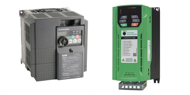
Figure 1. Two VFDs including models from Mitsubishi Electric and from Control Techniques.
Because of this linear output, this control method is called volts/Hz, or V/f (frequency). Linear or scalar control are both common terms for this method as well.
Closed Loop Vector Control
In mathematics, a vector is formed by two quantities operating at right angles to each other. In complex math, this is the combined effect of a real and imaginary quantity in 90 degree opposing planes. The final combined effect of these two quantities is the current delivered to the motor.
A vector controlled VFD still uses the pulse width control (PWM) to deliver a carefully controlled current to the motor coils, but the vector control determines how that current is calculated.
Field Oriented Control (FOC)
Those two right angle opposed quantities in this calculation are the motor’s magnetic flux current, and the torque current to produce a current for the field windings. This control method is often given the name field-oriented control (or FOC).
In a standard V/f drive unit, the calculation to produce current assumes that every increase in voltage will yield a consistent increase in current – that is, perfect linearity. In reality, this is not true, and any parameter change, including friction in an older motor, temperature from ambient or load conditions, and even changes in the load itself will cause the motor to respond to those changes. The effect is that the motor will not be able to respond to changes quickly.
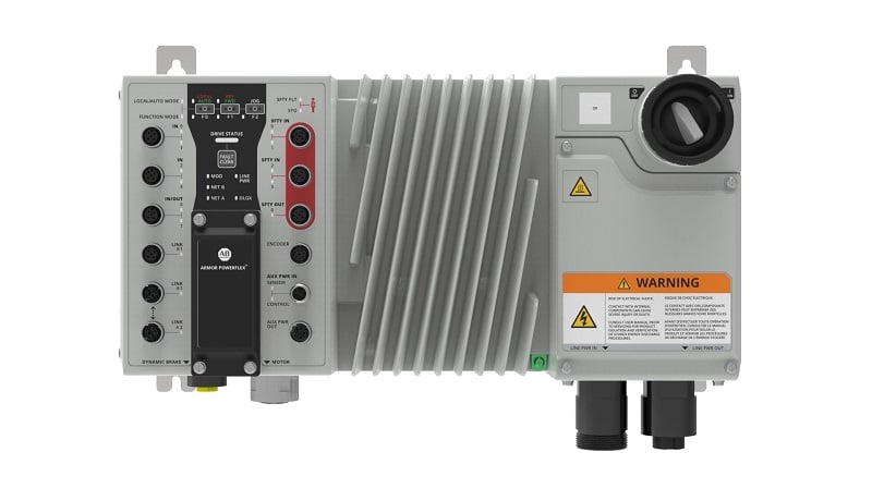
Figure 2. Rockwell’s new Armor PowerFlex VFD for on-machine control.
When the magnetic flux current and the torque current are measured and delivered independently, the controller can track those values, along with known conditions about the motor temperature and load, and can recalculate a proper output to the motor coils on a more continual basis.
Vector control requires more information about the motor:
Value of Current
The current components of flux and torque can be measured simultaneously in the drive using small Hall Effect sensors.
Motor Position
The motor position must be known very precisely in order to deliver the proper current components to each coil. In the past, this would have required an encoder or some other position feedback. In many cases, this is still used for increased accuracy, but modern microprocessors are better able to track motion based on the constant value of the current and a proper input of motor parameters. This is called open-loop control.
Motor Temperature
The temperature of the motor can greatly affect efficiency, with much of the current being dissipated as heat rather than magnetic force. By taking the motor and system into proper account, these temperature changes can be predicted. Although once again, sensor data may increase accuracy.
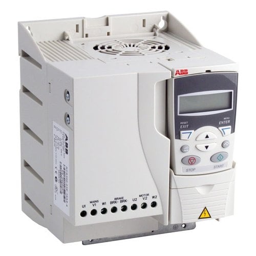
Figure 3. ABB’s ACS-850 VFD unit.
VFD Control Outputs
Knowing the value of the currents, position, and system characteristics, the output can be modeled and adjusted in real-time. This requires controllers that can perform the advanced calculations, often including a PI or PID controller for more accurate response, and it must be performed thousands of times every second. This is no small task for simple microprocessors, and until recently, the task was more expensive to accomplish.
As control electronics become more powerful, less expensive, and smaller, it is expected that more drive units will rely on the more accurate output provided by vector control.
Understanding Vector Control and Scalar Control
Next time you are designing or servicing a system, and a VFD with these control options presents itself, this may provide some background explanation on the differences and benefits of one system over another. As technology advances, new options are bound to appear on the horizon, and a bit of understanding can help to build a better system.
Copyright Statement: The content of this website is intended for personal learning purposes only. If it infringes upon your copyright, please contact us for removal. Email: admin@eleok.com