This article discusses some of the encoder types, signal types, and wiring needed for synchronous serial interface (SSI) protocol.
Many encoders use a form of signal communication called SSI (synchronous serial interface). Although the name contains the term serial, like the common industrial serial RS-232 protocols, this is a simple way to transmit information. This form of data transmission is the most common occurrence for absolute and incremental encoders feeding data back to a PLC or motion driver.
One common type of data output stream from rotary absolute encoders is the SSI. It is relatively simple to understand compared to other communication protocols but has one major advantage: The processor controls the data timing. To understand why this is commonly used for absolute, but not incremental encoders, we should investigate each type to contrast the signal streams.
Encoder Types
There are two main types of encoders: incremental and absolute.
Incremental Encoders
The incremental encoder is used for high-speed, continuous rotations where both velocity and position need to be known. They consist of a simple set of light and dark lines around a disk’s face, with light either blocking or passing through/reflecting depending on the optical type.
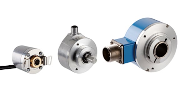
Figure 1. A few incremental encoders.
The output from these incremental encoders is usually two discrete signals, like an NPN or PNP sensor, high or low. This can determine rotation CW or CCW (clockwise or counterclockwise). There is often a third signal that creates a pulse once per revolution.
There are relatively few signals for incremental encoders, but they must be monitored at a very high speed (e.g., a high-speed counter module). Although your exact angular position can be tracked once the system has started, it’s impossible to know where you are at startup if power is lost.
Absolute Encoders
Absolute encoders solve the problem generated by any intermittent power loss by creating a unique series of patterns around the disk. At any time, a reading of that pattern can show the exact position of the encoder. These are useful for servo motors, which typically stop, reverse, and follow complex motion paths rather than being devoted to long constant-speed driving motions.
If the same communication strategy were applied from an incremental to a rotary encoder, each part of the disk pattern would need its own sensor wire. This would create as many as 12 to 14 individual signals. Instead, the data is sent through a serial interface to save wires and signal integrity—this is the purpose of SSI.
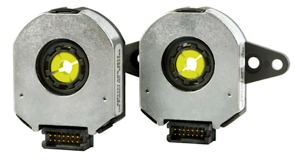
Figure 2. A modular absolute encoder.
Alternatives to SSI in modern encoders can also include advanced protocols, such as Ethernet, DeviceNet, Profinet, and others.
Signals used for SSI
There are only two signals required for the stream of information between the host and client device. This type of structure means that every encoder must have one SSI channel devoted only to itself. If you have two encoders or more, you need additional devoted SSI channels with connectors. This means there are no addresses requiring adjustment.
Host Device
The host device is the processor (PLC, servo driver, etc.). It sends a repetitive, high-speed clock pulse to the client (the encoder).
This client does not have, nor does it need, a clock of its own. Therefore, there is no need to set baud rate parameters for the encoder, so its circuitry can be simplified. Encoders spin very fast, and the data stream may be up to 14 bits for each reading, so these host devices must generate a high-speed clock pulse.
Any time an encoder is involved, expect the data transmission rate to be very high.
Client Device
The client encoder generates the second signal. Each time a clock pulse is received, a new data bit is placed at the outgoing pin of a shift register. The data stream reflects the light/dark pattern of the entire disk, so there will be 12–14 bits in series, then a repeat of the pattern.
The clock speed must be high enough that a pattern reading is taken before multiple pattern transitions have been crossed. The speed is often a function of cable length (i.e., longer cables reduce speed). A low transmission speed might be around 100 kHz or bits per second.
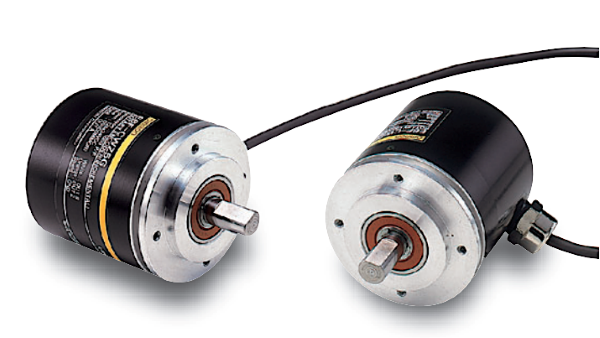
Figure 3. A rotary encoder.
For a 12-bit encoder, this would yield a total time of 0.12 milliseconds to send one entire pattern. For this 12-bit example, there are around 4100 patterns around the radius. To ensure a reading from each pattern, 0.12ms x 4100 = ~0.5 seconds for a full revolution. This equates to 120 RPM for the motor.
Any faster and the data stream will not keep up with the rotation speed. Keep this in mind when designing a system: Reduce the lengths of cables as much as possible or accuracy may be compromised.
A more typical rate may be upwards of 2 MHz, giving a max speed of over 2400 RPM, which is much more reasonable for a high-speed application.
Wiring for SSI Encoders
In a typical SSI device, there are six wires.
- The first two provide +V and Gnd to supply power for the integrated circuits in the sensor transducer.
- Each of the other two signals, the Clock and Data, consist of twisted pairs, denoted by C+ (or CLK, or Clock, etc.) and C-, and by D+ (or Data, etc.) and D-.
For most applications, a matching encoder and controller will have a keyed connector, eliminating the risk of incorrect wiring.
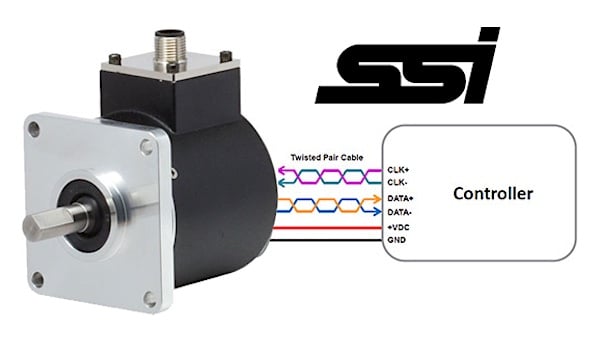
Figure 4. Wiring for SSI encoders.
SSI is simple data transmission from an encoder back to a host device. When choosing between an incremental or absolute encoder, the better bet would be an absolute due to its unique patterns around the disk. Keep in mind that the data transmission rate is very high when using an encoder, so reduce the cable lengths as much as possible.
Copyright Statement: The content of this website is intended for personal learning purposes only. If it infringes upon your copyright, please contact us for removal. Email: admin@eleok.com