Logic is critical for industrial control, and it usually looks like ladders, function blocks, or structured text. I/O controllers are designed to automate simple logic tasks and data functions.
Modern PLCs are capable of many thousands of tasks, including communication across many protocols, setting algorithms for motion and vision systems, and performing incredibly complex arrangements of logical control structures.
However, sometimes a control system doesn’t need quite this level of complexity. What if we simply need to connect a few I/O points, use some basic and/or logic, and turn some outputs on? And, importantly in today’s data-intensive analytical processes, what if we need to monitor some of those few I/O points from a remote location? For this kind of situation, most major PLCs are tremendous overkill.
ControlByWeb X400 I/O Controllers
A series of web-enabled I/O controllers forms the backbone of the product lineup from ControlByWeb, a Utah-based manufacturer. These controllers are not what we might consider normal full-featured PLCs that use the IEC languages and command hundreds of I/O, motion, and vision controllers, but they do allow many basic field-level logic control functions.
The power lies in the web connectivity, either by Ethernet, WiFi, or cellular connection based on the specific model, which provides an instant link to the cloud or remote data storage for monitoring and analytical purposes.
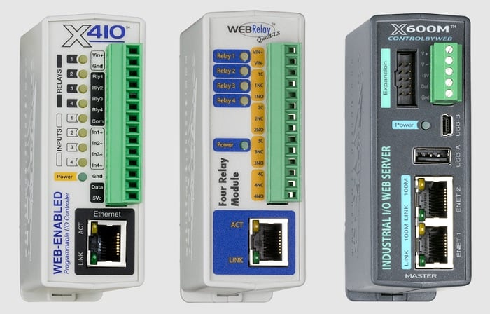
Figure 1. Examples of the I/O controller product catalog.
Each controller is designed for different I/O functions, like digital inputs and relay outputs, analog inputs, thermocouples, or protocol-specific communication nodes for data acquisition from another networked controller.
In perhaps the most stark distinction from traditional controller programming, the project development is performed entirely through a web server portal, password protected for project integrity. In other words, there is no software installation required to program these controllers.
This article will introduce the process of setting up a basic I/O control project on an X410W controller, including the steps for accessing the module and setting up the WiFi connection for those users who require such functionality.
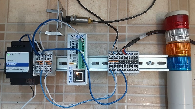
Figure 2. Test bench setup for the X410W I/O controller.
Connecting and Powering the I/O Controller
The first step, as normal, is to connect the hardware. Some of the I/O controllers from ControlByWeb can be powered with Ethernet (PoE), but most require a DC input. This X410W will be powered with a standard 24 vDC power supply.
The digital inputs are internally linked to the common DC ground, so unlike normal PLC module programming, we do not need to supply a separate common ground for the input terminals. We simply connect one PNP sensor output to In1+, and energize the sensor to ensure that the LED illuminates as expected.
If the controller is wired to a different power supply than the I/O field devices, you must connect a wire between the 0 vDC of the two power supplies.
Establishing Initial Connection With the Controller
These controllers do not have USB ports. The simple reason is that they are not programmed by downloading a project from any PC software through a normal serial (USB or RS-232) connection. We access the controller directly from an Ethernet connection.
Connect the Ethernet cable, and ensure that your computer is on the same network, but with a different IP address than the controller. At the initial connection, the IP is 192.168.1.2 by default. You can change it immediately if needed, but you must connect before editing any connection parameters.
For info on how to set your computer’s IP address, follow our guide.
Caution: if you are connected to an Ethernet network that already has a lot of connected devices, be sure that NONE of them are already using that 192.168.1.2 address or there will be an IP conflict. For this reason, it might be handy to disconnect your PC from the network and just use one single Ethernet cable between the X410 and the computer.
Once connected and on the same network, open a browser and type in 192.168.1.2 and you should see a screen that looks like the one below, although you may have some of the I/O points ON if your sensors are energized.
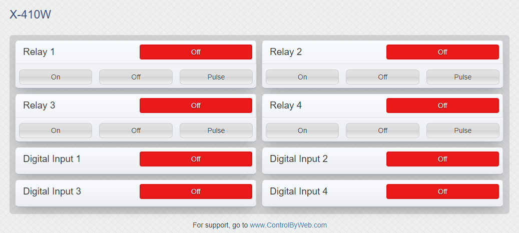
Figure 3. Accessing the web server in monitoring (non-admin) mode.
From this screen, we can view the I/O status, but we can’t program anything. This is very useful for monitoring as an HMI, but we need to enter the setup screen for the fun to really begin.
Enabling WiFi and Setting IP Addresses
Entering the setup configuration requires admin access, which is easy with factory defaults, but should probably be changed if security is a concern.
In the web browser, type “192.168.1.2/setup.html” and the credential entry box will appear. Use “admin” as the username and “webrelay” as the password (without the “ symbols).
With the X410W, we can enable the WiFi so that a hardwired connection is no longer necessary. This allows you to log in and adjust the parameters from anywhere with a WiFi connection.
Access the WiFi menu from the left sidebar of the screen.
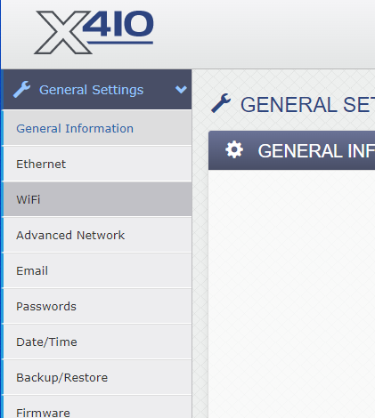
Figure 4. Accessing WiFi settings.
The system will scan for available networks, which will appear in a drop-down menu. You also need to provide the network password.
At this time, it might be beneficial to turn DHCP off and choose an appropriate IP address so that you can type this address into the browser to access the server across the network. In my own case, I chose 192.168.1.27 for this controller.
At the bottom of the screen, click the ‘Submit’ button to save the changes, then reboot the device.
If your computer is connected to that same WiFi network, you should be able to disconnect the Ethernet cable, type the newly assigned IP address into the browser followed by “/setup.html”, and enter the credentials again. I recommend keeping the Ethernet connected during setup. If the router changes the IP address, or if you enable DHCP, the IP address will change and you will no longer be accessing the server. If you don’t know the new IP address, you might be locked out! Keeping the Ethernet connected ensures that you always have a back door into the system until you have the unit completely configured.
Now we are wireless!
Setting Up I/O Devices
The final step of this tutorial process will be the setup of one control action that monitors the sensor for an input signal and relates that to one of the output relays.
Later on, we can use that input action to trigger a more data-driven response, such as sending an email with the current I/O statuses or uploading a data packet to an MQTT broker for long-term data storage, but for now, we’ll simply energize local I/O points.
Expand the I/O Setup on the left menu and give a name to one of the digital inputs. This might appropriately be the name of the sensor, like “inductive metal sensor” in my case.
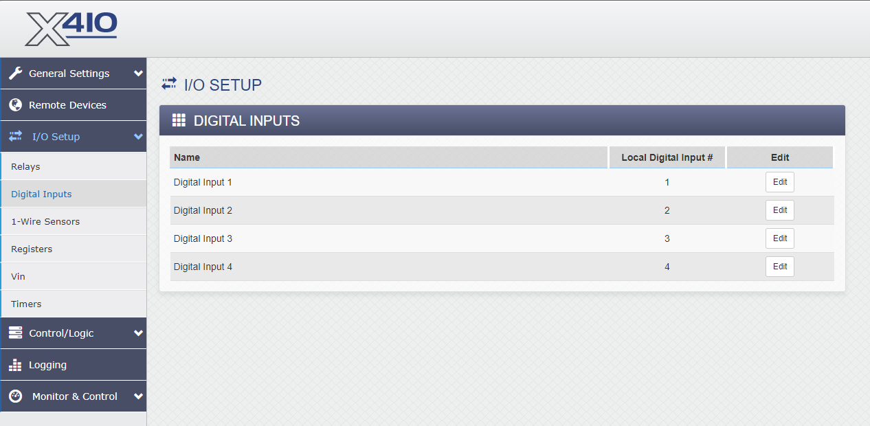
Figure 5. Naming digital inputs and setting various input parameters.
Click “Edit” and enter the relevant info.
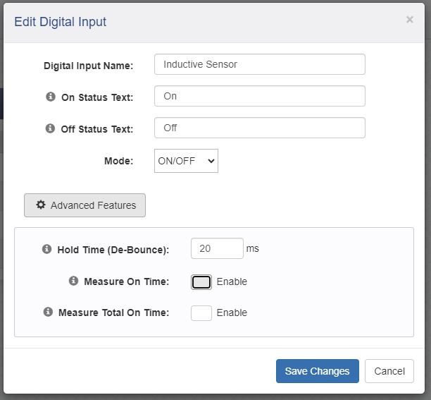
Figure 6. Input details for I/O and timing status.
Advanced features for inputs also include debouncing for mechanical switches and relay contacts. You may also enable measuring “On Time” and “Total On Time” which can be logged for analytical use or included in an emailed/uploaded data packet. Understanding sensor usage times can be a great source of insights.
You could also set up one of the relays if you are connecting an output device. I simply use the built-in relay to test I/O functions. I can hear the click and see the LED, giving me proof that the program is working properly.
Configuring an I/O Control Action
Finally, the last step is to create an I/O task, much like a rung of logic in a ladder program.
Conditional tasks are those which act when triggered by an input. Scheduled functions will perform a pre-set action at a specific time or on a recurring basis, and reboots can monitor other networked controllers and reset machines if network coms drop out.
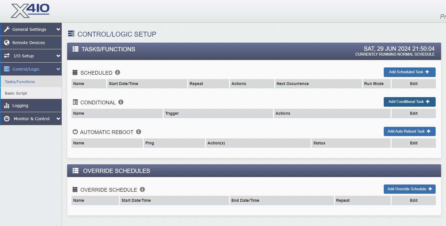
Figure 7. Logic task menu.
Add a new conditional task and choose the inductive sensor (or your own sensor) as the if trigger condition. You can certainly add a second sensor and experiment with and/or logic; it’s quite simple.
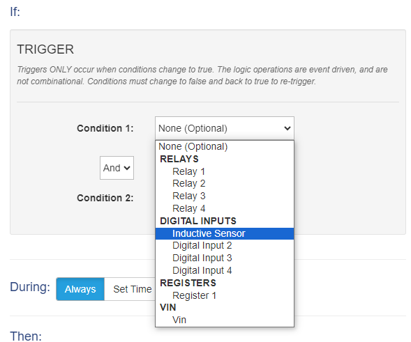
Figure 8. Setting up the if (condition) part of the if/then statement.
Likewise, we need to set the resulting then action statement.
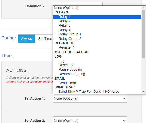
Figure 9. Setting up the then (action) part of the if/then statement.
As you can see from the menu list, the condition can trigger any sort of response including relay outputs, pushing data to an MQTT, email alerts, or triggering log functions. Be careful when setting up email triggers. If you accidentally connect this action to a trigger that will pulse every few milliseconds, you will spam your poor recipient’s email server and probably be blacklisted. Only use this action when there will be a significant, deliberate delay between trigger events.
Note: If you choose to turn the relay ON when the sensor is energized, you need to remember to make a second action that turns the relay OFF when the sensor is de-energized again!
When you make a change, the action is immediately applied in the controller, you don’t need to worry about run/stop modes or downloading the project to the device; you simply have a portal into the program that is running on the device at any time.
Advanced Functions
Although this device is innovative in the sense of web sever-based project development, we have only performed basic I/O actions so far. This is no different from even the most basic PLC. In future tutorials, we’ll have a look at more advanced functions such as logging data, interfacing with MQTT brokers, and sending periodical status emails or alerts to gain faster access to critical data points.
Copyright Statement: The content of this website is intended for personal learning purposes only. If it infringes upon your copyright, please contact us for removal. Email: admin@eleok.com
