Learn about serial and parallel data communication modes, errors, and flow controls used in connecting legacy and even some modern point-to-point network devices.
Parallel transmission allows multiple bits to transmit simultaneously over multiple wires, enabling a device to send and receive data at high speed, while serial communication involves the transmission of bits one after another over a single wire. In this article, we’ll explore both modes of data networking and the error detection and recovery techniques deployed to ensure data integrity.
Communication Between DTE: Parallel or Serial
Data communication between computers or sets of data terminal equipment (DTE) is done using digitally coded information consisting of 1s and 0s. In data communication terminology, data is equivalent to a block consisting of one or more digitally codded characters. Some control data must also be transmitted along with useful appended bits, e.g., data that guards against transmission error. The distance between two entities is important since it determines the method used. The distance could be a couple of meters to several hundred kilometers.
Transmission Modes: Parallel or Serial?
Effective communication between DTE <-> DTE depends on the methodology which relies on factors like distance between devices, required speed, and maximum cost. As already stated, the distance over which both parties communicate determines whether parallel or serial communication should be employed. Almost all communication is parallel inside the computer while external computer-computer communication is usually serial.
Parallel communication is used over short distances, which means that the entire integer, whether byte, word, or long word, is transmitted at the same time. Either 8, 16, or 32 conductors must be used (respective to the integer size), but this would make the parallel transmission very expensive over a long distance, although it would be fast. The optimal solution over long distances, then, is serial communication. In serial communication, only one bit is transmitted at a time. Hardware-wise, only 2 or 4 wires are required, but the transmission speed becomes significantly lower.
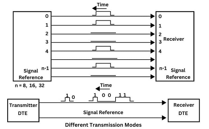
Figure 1. Parallel vs. serial transmission modes between the sending and receiving devices.
Modes: Simplex, Half-Duplex, and Full-Duplex
In daily life, we observe that when two people communicate, we can distinguish between one-way communication, just like a teacher’s lecture, in which one person speaks and the rest listen. In two-way communication, we might imagine a conversation between two people. The aforementioned concepts are also applicable to computer communication. The most common modes of communication between devices are:
Simplex: The communication is in one direction only: transducer or transmitter sending data to a database by way of a pre-determined schedule.
Half duplex: Two parties take turns to transmit data to the other party. Two conductors are required for communication, a +data and a -data line.
Full duplex: Often simply called duplex, two devices send data to each other simultaneously. This requires four conductors because each device transmits data in its own pair of wires (+ and – data).
The parallel transmission of data makes transmission control easier since the receiver obtains whole words of data, highlighting the need to count bits received. On the other hand, serial communication must include the transmission of control information for instance the receiver must know the following:
- Transmission speed in bits per second (bps)
- Where the beginning and ending of each data item are situated.
- Where the beginning and ending of the entire data block are situated.
These factors are generally called synchronization factors. Generally speaking, the transmitter and receiver must be synchronized to perform problem-free data transfer.
Asynchronous Communication
This sort of communication is employed when the communication takes place at random times, such as between a user tapping a keyboard and the computer. The time between any two transmission cycles is of random length. The two devices must be synchronized to establish communication. This can be achieved by the transmitter sending a character message that includes a leading start bit to indicate that useful data is about to follow, as in Figure 2.
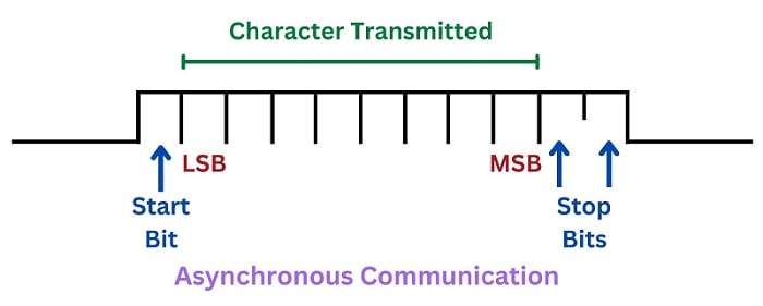
Figure 2. The structure of an asynchronous data transmission, with start and stop bits shown.
The two stop bits mark the end of the message. When the receiver reads the character, the two parties must be synchronized again as a part of the transmission of the next character. This method of synchronization is called character synchronization.
Synchronous Communication
The communication is employed when large blocks of data are to be transmitted between computers. The entire block is viewed as an entity and is enclosed in two or three bytes with additional information, one at either side and sometimes two at the trailing end. These bytes correspond to the stop and start bits of asynchronous communication but are called start of frame and end of frame bytes, respectively.
Depending on the clock rates of the transmitter and receiver, if the two speeds are equal, the communication is called synchronous. If they differ, it is called asynchronous. When configuring the transmission rate of a communication line, the term “Baud rate” is used. The baud rate is the number of bits transmitted per second. Common transmission rates are 110, 300, 1200, 2400, 4800, 9600, and 19200 bits/second.
Transmission Errors
Data distortion is a common phenomenon when transmitting data serially over a long distance, e.g., communication over the telephone network. Therefore, it is necessary to check whether the data transmitted is correct. To make sure that the information received is correct, the receiver must be given the means to verify this data. If the transmitted data is not intact, it must be possible to correct the error or retransmit the data.
Parity Checking
It is the most common type of error-checking technique on data that is transmitted in small portions. The parity checking means the sender calculates the sum of ones in the message to be transmitted. If this sum is an even number then even parity is employed, and the parity bit is set high. In case of odd parity, the parity bit is set low. This parity bit (even or odd parity bit) is then appended to the message for transmission as in Figure 3.
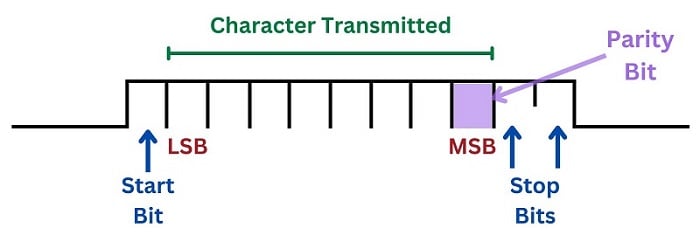
Figure 3. The parity bit is the 8th or final bit of the byte.
The parity bit then enables the receiver to check the sum of bits and compare it with the parity bit to ascertain whether any error has been detected.
Flow Control
When the data is transmitted, the receiver has to buffer the incoming data. Buffering may be necessary since the computer may be busy with other tasks when the data arrives. If a small amount of data is transmitted, there are usually no problems, but if the data is large, the buffer may need to be bigger. In such cases, the receiver must be able to temporarily stop the flow of data until the contents of the buffer have been consumed and transmission can be resumed. This is called flow control.
Communication Protocols and the ISO Reference Model
Error checking and flow control are the two most important functions of communication protocols. Communication protocols are the set of rules and conventions that must be adhered to by communication devices for communication to work properly. The communication protocols might also cover:
- The structure and format of data to be transmitted, e.g., the number of bits per element.
- Type and order of messages to make the transmission as reliable as possible.
To facilitate the development of protocols, the International Standards Organization (IOS), at the end of the 1970s, defined a reference model for standard communication protocols. This model became known as the ISO reference Model for Open system Interconnection (OSI) and described a structured approach to data communication, Ever since, this model has had a strong impact on the computer and data communication industries. Nowadays, all networks are based on this model to a larger or lesser extent.
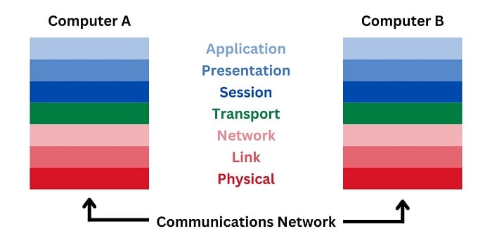
Figure 4. The reference model for Open System Interconnection (OSI).
The model divides the logical structure into seven layers. The three lowest layers are dependent on the network, while the three uppermost are linked to the application. The middle layer, the transport layer, constitutes an interface between the upper and the lower layers. In sum, each layer communicates with the corresponding layers in another computer.
Following are examples of applications that employ the OSI model for communication:
- Remote terminals read process field data and transmit it to a central system.
- The communication between the two centers
- Workstations fetching and sending files from or to a file server
Network Communication
Understanding serial and parallel communication, while important for development operations, might not be an everyday concern for all engineers. But it’s important to know it quite well when upgrading or interconnection various systems, which is common in legacy equipment.
Copyright Statement: The content of this website is intended for personal learning purposes only. If it infringes upon your copyright, please contact us for removal. Email: admin@eleok.com