Before tuning a motion axis, you must define the axis. If the control system doesn’t understand the axis properties or specifications, it can’t be expected to effectively complete the tuning process.
When I need a definition for a word, I look at a dictionary. Or rather, back in 2002, I would have looked through a dictionary; these days, I just Google it. Consider, for a moment, how you go about using a word in a sentence. If you don’t know what a word means, you can’t (or shouldn’t) use it in writing or in speaking to other people. Before you can use a word, you must know the definition, the pronunciation, and how it fits in context with the words around it.
What Does it Mean to “Define” a Motion Axis?
Let us take this same idea and look at a ‘motion axis’ through the same lens. Before a motion controller can run the axis or apply the specified tuning parameters, it must know a good deal about how the axis works. Does this axis spin in circles? Does it use a spinning lead screw to create horizontal motion from rotational energy? Does it use a quadrature encoder? Or maybe an SSI encoder?
Let’s start breaking down axis definitions into manageable pieces. There are a multitude of companies that offer different styles of axes to set up, each within a unique software IDE. Below is an example of Yaskawa’s SigmaWin+ program, which is engineered for servo motion.
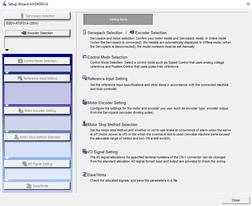
Figure 1. Yaskawa’s SigmaWin+ servo tuning program.
Another example, and the one we’ll use for demonstration, is Delta Motion’s RMCTools programming platform. The major characteristics tend to remain generally the same from manufacturer to manufacturer. Between SigmaWin+, RMCTools, and others, there are several similarities to point out: Control Mode Selection, Input References, etc.
Because Delta Motion engages in both servo and linear hydraulic motion, as well as being compatible with a multitude of other manufacturers’ equipment, we are going to rely on this platform as our example.
Axis Definition Properties
Let’s give this window a brief run-through. We are defining the axis type, the control loops, control modes, the kind of output, the style of feedback, and the number of feedback types. If you get as far as ‘axis type’ and you’re already totally lost, don’t worry; a bit more reading and you’ll be squared away on it.
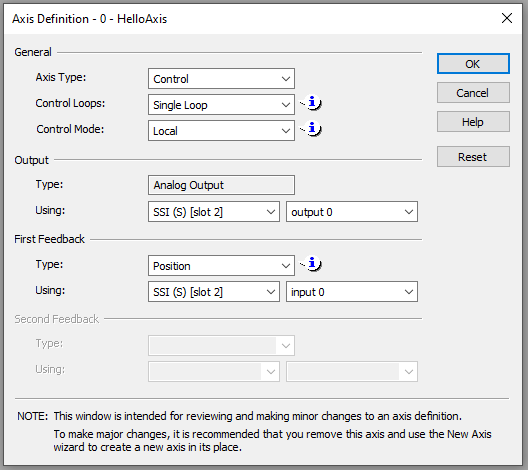
Figure 2. The Axis Definition window inside RMCTools from Delta Motion.
Axis Type
When it comes to axis types, you’ll find the majority are called Control Axes. Control axes allow you to work with equipment in the field directly from the controller. In contrast, another axis type would be a Reference Axis or a Virtual Axis. These are designed to provide feedback remotely to another control system or synchronize multiple pieces of equipment that all need to work together in a concerted motion.
Control Loop
The Control Loop itself will be covered later, but the configuration of the NUMBER of loops must occur first. Most applications will have a single control loop, but there are some that can have two loops. The RMC151E from Delta Motion can change from one control loop to another in the middle of a single movement. A move might begin with traveling to a destination (Position Loop) but then transition to a grabbing force at the end (Force Loop). Your application will determine the number of loops you have.
Control Mode
With the development of high-speed data communication, such as EtherCAT, it is now possible to control other devices with very high precision. This speed and precision allow external systems to run independently, remotely controlled by the overarching system.
It is most common to run in Local mode, where calculated positional commands may come from an external networked controller, but the motion controller receives the feedback and processes the outputs by itself.
Output Type
This one is easy: if you are running in the Local Control Mode, you will be using the Analog Output native to the RMC axis card.
Output Usage
The RMC150 that I used for demonstration has 2 control axes per card. Let’s say you only plan to use one axis. The Output Usage selection allows you to choose which axis output to use. If Axis 0 and Axis 1 are available, a dropdown menu allows you to choose between them. The same applies if you have multiple cards to choose from.
Feedback Type
Our feedback types can differ based on your application. Sometimes you want to specifically track position. Other times, speed is your primary driver. If you are picking up something extremely delicate, you may want a pressure or force driver that allows you to apply enough force to lift, but not so much force that you destroy the payload. Think of this like picking up an egg, too much force and it’s done for.
The dropdown options are pictured below as an example of how it looks during set-up.
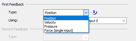
Figure 3. Choosing a feedback target (real-world physical sense) type.
Feedback Usage
The final step in setting up your axis with RMCTools is to determine what kind of feedback you are using. If we add a feedback card in slot 1 with SSI and another card in slot 2 with MDT, this section allows us to choose which card and channel are being used to get the feedback for each axis. This is very similar to the Output Usage except on the other side of the I/O.
Configuring the Axis With Parameters
Although we have now established what kind of control we are using, as well as the source and destination of signals, the next step will be to provide the physical characteristics of the axis. Linear, rotary, resolution of the encoder, voltage scale of feedback devices, and the other parameters that will enable the algorithms to calculate the commands during operation.
Copyright Statement: The content of this website is intended for personal learning purposes only. If it infringes upon your copyright, please contact us for removal. Email: admin@eleok.com