Learn to discern between textbook and real-life scenarios and use consistent troubleshooting methods to simplify and correct errors in parallel circuits common in industrial control systems.
The simplest form of circuit configuration, the series resistance circuit, does not appear in the vast majority of industrial control circuits. This is surprising since it seems to be presented in classes as a very common circuit. But when it comes to parallel resistor circuits, should we expect the same absence?
Generally, industrial electricians agree that real-world circuits very rarely follow the neat, clean circuit diagrams presented in textbooks and formal courses. The fundamental concepts still apply, but the uses, terms, and definitions can vary depending on the industry.
Series resistance circuits are usually the starting point for explaining voltage drops and current, but these circuits rarely appear inside control cabinet and machine wiring. In contrast, parallel circuit configurations are very common. However, there are a few specific concepts of parallel circuits to emphasize for use in industrial control systems.
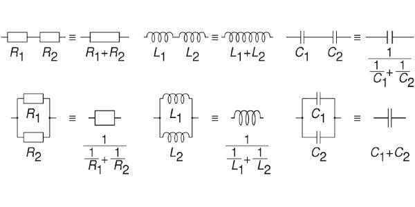
Figure 1. Comparison of effective resistance, inductance, and capacitance of two resistors, inductors, and capacitors in series and in parallel. Image courtesy of Cmglee. [CC BY-SA 4.0]
One point to consider is that the words ‘series’ and ‘parallel’ can refer to either the resistive load devices (outputs) or the control switches and buttons (inputs). The wires’ connection would look quite similar, but the effect on the system and the troubleshooting strategies are quite different.
Parallel Loads
The first fundamental concept presented dealing with parallel resistors is that they will experience the same voltage drop, regardless of the relative resistance values. Understanding this is critical in the case of industrial load devices because they all require identical operating voltages. Not only that, the required voltage happens to be the entire power supply voltage!
For example, common load voltages would be 24 volts DC or AC, perhaps 120 volts AC, or even 230 volts AC for some contactors. In each of these cases, the power supply outputs exactly the required voltage for the device. This means that when we measure a load device’s voltage, it should either be 0 volts (off) or full supply voltage (on) — nothing in between.
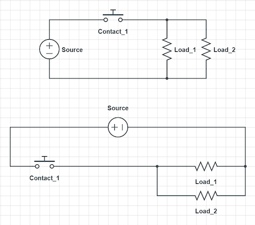
Figure 2. A normal parallel load circuit as seen in a common textbook example (top). The equivalent parallel load circuit translated to a line or ladder diagram with power on the left vertical side and ground on the right (bottom).
Placing two load devices in parallel still provides both of them the required voltage, and therefore they both operate properly. The one requirement is that NO load device may have another load device placed in series. Otherwise, the voltage of each one will be too low for proper function.
This is not to say there is no effect from parallel circuit connections. Every device in parallel effectively provides a new path for current to flow, increasing the overall current consumption from the source — be careful to choose a sufficient power supply! If the current increases, it indicates an overall drop in the total equivalent resistance of the circuit.
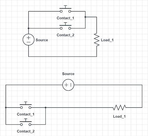
Figure 3. A normal parallel contact circuit as seen in a common textbook example using Normally Open contacts (top). The equivalent parallel N.O. control circuit translated to a more common industrial line or ladder diagram (bottom).
A common form of electrical schematics in industrial settings is the ladder or line diagram. This format places every logical combination of inputs and outputs in parallel with each other. Each ‘branch’ is a small parallel circuit in itself. Sometimes, a single line or ladder ‘rung’ will contain multiple loads. In these cases, seeing them in parallel with each other is guaranteed.
Parallel Resistance Formula
There are times when it is important to know the formula to calculate resistance. If the resistors are the same value, the total resistance is found by simply dividing that resistance by the total number of resistors:
For equal resistance values:
$$R_{total}={R \over Number~of~Resistors}$$
But for non-equal resistor values, the calculation is a bit trickier:
$$R_{total} = {1 \over {1 \over R_1} + {1 \over R_2} + {1 \over R_n} }$$
In all cases, the total resistance will be lower than even the smallest resistor value, and adding more resistors will only serve to keep decreasing the total resistance.
Parallel Contacts
In the case of circuit analysis, it helps distinguish between ‘inputs’ and ‘contacts’. Usually, those two terms mean the same thing. However, when you connect inputs in series and parallel, you cannot always accomplish this with all inputs.
Sensors and ‘solid-state’ inputs cannot be placed in series (and not always in parallel either). However, a ‘contact’ is a physically opening and closing control device such as a button, quarter-turn switch, or limit switch, and these are great for series or parallel connections.
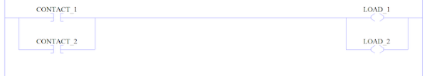
Figure 4. A more typical view of a ladder diagram with symbols closer to what is seen in a PLC control diagram. This circuit shows both parallel contacts on the left and parallel loads on the right.
When placed in parallel, two contact devices provide multiple ways to activate the load device. The concept is equivalent to a digital OR gate in which one switch OR the other may activate a load. This is useful when there are multiple start buttons or any other case where two or more controls should energize a load.
What about Automated Systems?
When a PLC input or output module is included in a system, it is extremely unusual to see either switches or loads in parallel connected to the same I/O terminal. Two reasons for this fact:
- Each terminal should have a label (or tag) that states which unique input device it happens to be monitoring.
- Multiple output devices can overload an output terminal on a PLC – they aren’t as robust at handling current as a physical button or switch.
One case in which is a parallel circuit is connected to a PLC is the case of a diode placed across an inductive load device, such as a contactor or solenoid. This diode, often called a snubber diode, reduces the flyback voltage and prevents damage to a PLC output. If you experience continual damage to an output module, verify that you have diodes connected to any inductive coil load devices.
A Review of Parallel Circuits
Industrial control circuits may have either parallel loads or contacts. Parallel loads should always have either full source voltage or zero voltage, and they will all be active simultaneously. Parallel contacts will provide an OR logic construction providing multiple branches through which the load may energize.
Copyright Statement: The content of this website is intended for personal learning purposes only. If it infringes upon your copyright, please contact us for removal. Email: admin@eleok.com