Start to understand the difference between analog and digital communications, and read a few examples of how analog, digital, and discrete signals can be used in a control system.
Communication between devices is one of the most critical, yet confusing concepts within a modern control system. Much of the confusion is due to many years of evolving protocols and technologies—some simple, and some far more complex.
There are two main categories of communication methods involving analog and digital signals, respectively. But even within the category of digital signals, there are many different strategies to explain how controllers can share process data.
In this primer article, we’ll talk about the high-level concepts of digital and analog communication and give context for how control engineers interact with these concepts on the job.
Understanding Analog vs. Digital Signals
Every experienced control engineer is familiar with the difference between digital and analog voltages. These two contrasted voltage strategies are explained in the scope of any digital electronics technical or engineering course. Upon further practical examination, the same concepts appear when creating a communication channel between two devices. However, in this case, the difference is not quite as simple as a textbook might present.
Analog communication between devices is a common go-to method of sending data that is more complex than a simple on-off control like a pushbutton or switch. Analog signals are still simple but can present a wide array of data with a single wire.
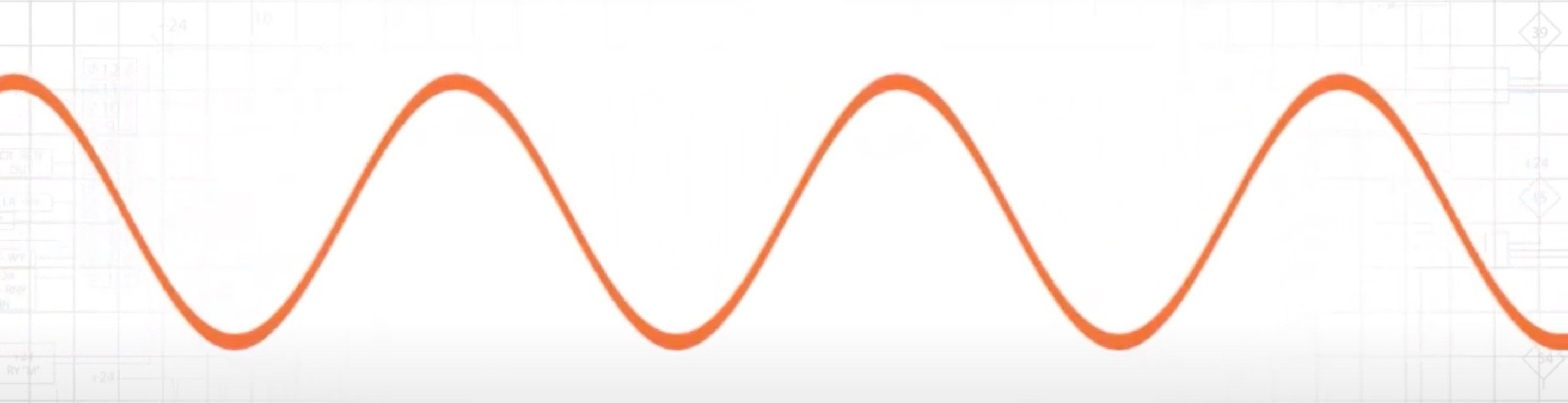
Figure 1. An example analog signal.
Digital communication is more abstract. The term “digital” can refer to either single discrete signals, or it can refer to the stream of binary data used by Ethernet, DeviceNet, Modbus, or nearly every other serial data stream.
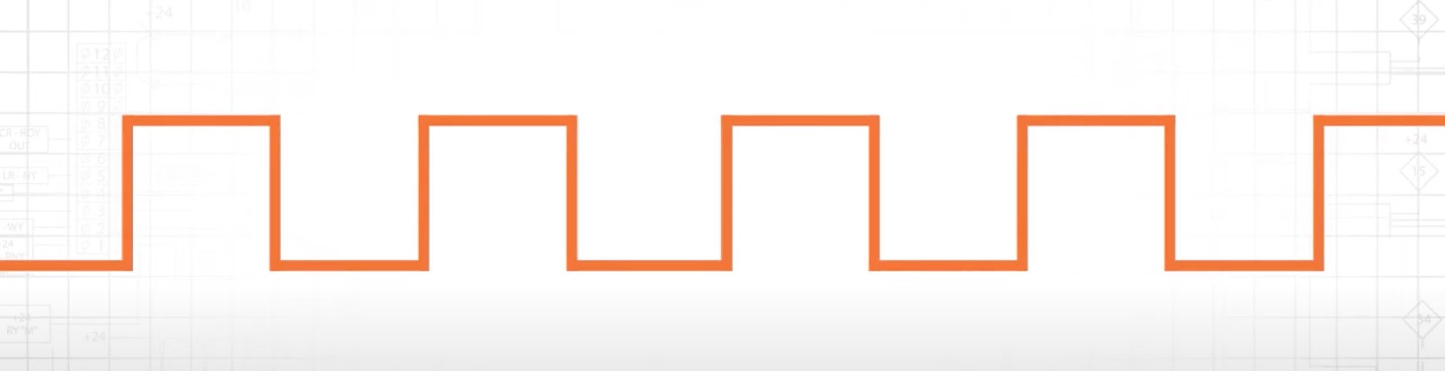
Figure 2. An example digital signal.
Because of this complexity, the digital communication category will be discussed in both the discrete and digital scenarios.
Analog Communication
The term analog refers to any voltage with more than two distinct possible levels. Most microprocessors that drive digital controllers prefer two-state voltages—usually called simply “on” and “off”—the lowest and highest voltage possible, depending on the power supply of the system.
However, outside of the computer, those voltages may be anywhere within that range of minimum to maximum. There are a few common standards depending on the industrial system.
For microcontrollers, such as the popular Arduino and other related boards, a voltage between 0 and 5 V can be read by an analog-to-digital converter (ADC. More common industrial voltages, like 24 V systems, often rely on 0–10 V levels.
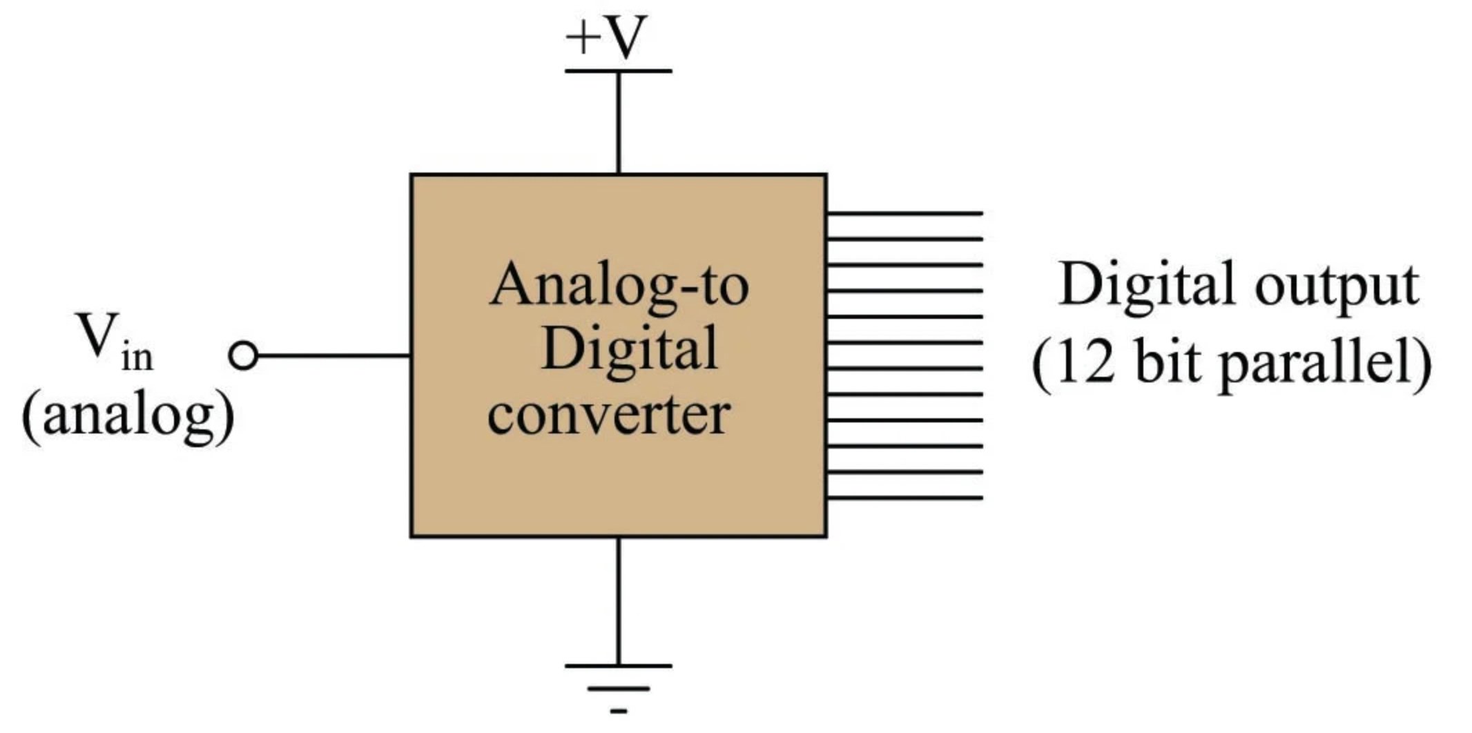
Figure 3. An example analog-to-digital converter.
If the voltage drop of a long wire might present inaccurate readings between sending and receiving, a signal may be presented as a constant-current supply, with 4–20 mA being the level of data from the source.
It is quite common for controllers to contain an ability to read individual analog signals from sensors, but another matter to supply an analog output. A scenario where this might be critical is the driving of a VFD without having an Ethernet or other network adapter. The speed must be controlled more carefully than on/off; therefore, the controller must supply an analog signal to the VFD. Again, this can be either voltage or current in most cases.
A less common yet ingenious use of analog signals is to use different voltage levels to provide entirely different data—not simply changing the value of a single data type. For example, perhaps a system needs to send the value of six different sensors from one device to another. By sending a single analog signal with 26 (or 64) different levels, the receiving controller can immediately identify which combination of those six sensors are on and off with a single wire.
Discrete Communication
Those voltage levels listed in the previous section, such as 0–5 V or 0–24 V, are equally relevant in discrete communication systems. Rather than using an entire range of signal levels, they would instead be expected to exist at either 0 volts, or at the maximum voltage—nothing in between.
Every signal is a different wire in these communication systems. If that same VFD in the previous example needs a signal for both RUN and JOG, that must be two separate signals.
The increased number of wires in the bundle can present problems, so it is uncommon for this discrete communication method to be used for transferring large amounts of data. Its strength is in cases with small numbers of simple data signals, or when the devices are physically separated, making network cables ineffective. These individual signals are far easier to troubleshoot than within a complex network.
Contrary to an often-confused opinion, it is absolutely possible for AC voltages to be used for discrete control systems. In fact, this is quite common. The voltage might be 120 vAC, and if the sensor is supplying 0 V, it would be off; but if it is supplying 120 V, the signal is on. The only difference is that the input module of the control device must be rated for at least 120 vAC or damage will occur.
In reality, the voltages are not 0 and full supply voltage. Every device will have a tolerance listed in a datasheet that provides guidance on how low can be considered “off” and how high can be considered “on.” If a significant voltage drop forces a 24 V signal to fall below 21 V (for example), the control may not recognize this as either on or off, and the source of the problem must be resolved for proper operation.
Digital Communication
This final category cannot be thoroughly explained and defined within the scope of a single article.
Digital communication can occur when directly connected from one device to another or as a part of a large network. These digital protocols exist as a series of discrete bits sent down a single transmit (Tx) or receive (Rx) wire. The speed of these bits, as well as any addresses of the controllers or the actual content and purpose of the data streams, is completely up to the definition of the protocol.
In a sense, digital communication can be thought of as Morse code with dots and dashes representing the two voltage levels of high and low.

Figure 4. A series of digital communication protocols.
Some common examples of this type of communication would be Ethernet, RS-232 serial, ProfiNet, DeviceNet, ControlNet, Modbus, and many others. For further guidance on any of these individual protocols, it would be advisable to study them in greater depth.
What use cases would you like to see explored when determining which communication protocol to use in a given application? Share your questions or thoughts in the comments below.
Copyright Statement: The content of this website is intended for personal learning purposes only. If it infringes upon your copyright, please contact us for removal. Email: admin@eleok.com