This article investigates the basic principles of inverters, different types of DC-to-AC conversion, and common applications for generating AC voltage in manufacturing.
With greater electronic prevalence, increasing renewable energy sources, and industrial automation processes, inverters have become ubiquitous electrical equipment for supplying AC power from a DC source.
What is an Inverter?
Most power supply designs include a section called a rectifier which takes the incoming AC wave and turns it into a seedy DC voltage. But we can’t always rely on an AC input from the building mains power into our system.
An inverter is a device that takes a direct current (DC) and turns it into an alternating current (AC). There are many uses for inverters and common places where one might find an inverter, including:
- Industrial manufacturing
- Renewable energy (wind generators and solar farms)
- Battery backup systems
- AC motor variable speed drives
- Electric cars
Inverters Turn DC Power into AC Power
Traditionally DC power conversion was achieved through a motor generator set, where a motor operating on DC power directly turned a generator to produce the required AC power. The opposite of this, an AC motor driving a DC generator was called a converter, hence the name inverter when applied to a DC to AC gen-set, the name stuck. An alternate version used a mechanical switching mechanism housed in a vacuum tube that switched the polarity of the direct current at the appropriate intervals.
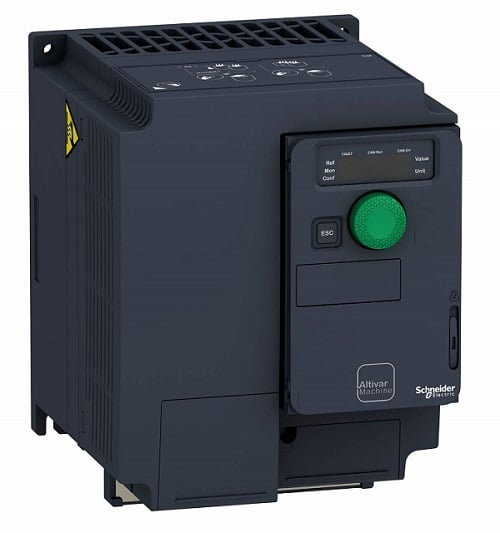
Figure 1. A typical power inverter.
Most modern inverters function as solid-state devices that require no moving parts to turn DC into AC power. This allows them to create a higher level of reliability and provides better efficiency. Inverters have become increasingly complex and can supply reliable power capable of powering even sensitive electrical equipment. Clean sinusoidal power is important for the longevity of motors and sensitive equipment using inverter-supplied alternating current.
How Do Inverters Work?
Most modern inverters utilize some form of H-Bridge circuity to change the polarity of direct current. In most cases, the lower voltage DC current needs to be amplified to match the voltage of the AC it will be supplying. The act of switching DC voltage naturally creates an alternating current because, in principle, AC power is an electrical current switching polarity at a certain frequency.
H-bridges consist of four switches that can be used to switch the polarity of a load through an H-shaped circuit, so the current can flow across the H in either direction depending on switch orientation These circuits are commonly used for reversing motor polarity, as exemplified by the circuit diagram below.
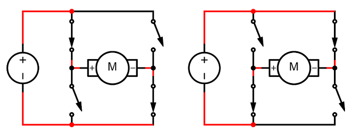
Figure 2. A simple H-bridge circuit can be used to effectively switch direct current polarity.
A basic H-bridge can supply alternating current at the correct frequency, but the power output has a different waveform than what should be supplied by the electrical grid.
When DC power polarity is switched through an H-bridge, the resulting waveform is square. For some applications, square waveforms are not detrimental as long as the wave frequency is within the appropriate range, however, they can be problematic for more sensitive electrical equipment and the operation of AC motors. These sensitive electronics require a purely sinusoidal alternating current waveform for proper operation and longevity since square waveforms can damage certain equipment.
Types of Inverters
Inverters can be categorized based on the type of AC power they produce. AC power generated by the grid is of a pure sinusoidal shape and alternates smoothly between high and low voltage according to the shape of a sine wave.
Since basic H-bridges technically only switch voltage forward or reverse, there is no way for them to achieve a sinusoidal waveform directly without added components. The complexity of the added components dictates the waveform produced by each type of inverter. The three most common waveforms produced by an inverter are:
- Square waveform
- Modified sine wave
- Pure sine wave
The names of these types of inverters are fairly intuitive, the cost of each inverter is directly related to how closely they can achieve a sinusoidal AC waveform.
Square Wave Inverter
A square wave inverter is simply an H-bridge switching current polarity to create a waveform of the correct period and amplitude. The applications for this type of inverter are limited because of the nature of the AC power they produce. Square wave inverters are the simplest inverter design and feature low cost and in some instances higher efficiency rates than modified sine wave or pure sine wave inverters.
Depending on the application, square wave inverters can create a simple cost-effective way of converting DC to AC power, as long as the equipment being powered is not detrimentally affected by non-sinusodal waveform AC.
Modified Sine Wave Inverter
A modified sine wave inverter uses an H-bridge circuit and a high-speed switch. In a modified sine wave inverter, DC power is alternated by the H-bridge, while a high-speed switch pulses the current in a way that the average voltage mimics that of sinusoidal waveform AC power. A microcontroller switches the power with varying on-off pulses (called pulse width modulation, or PWM) so that the average voltage at any period in time mimics the voltage one would expect of sinusoidal power in the wave period.
The result of this switching action is a stair-stepped waveform that is much closer in shape to that of a sine wave, but it’s still not exactly sinusoidal. For many applications, this type of AC power is acceptable and can be used with most types of electronics and motor applications.
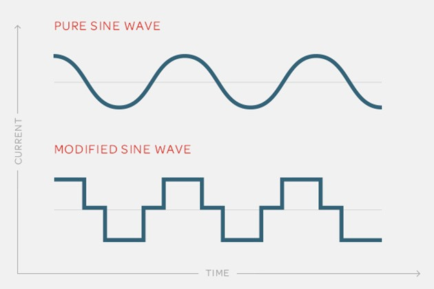
Figure 3. A modified sine wave inverter has the same period and magnitude waveform as pure sinusoidal power, but its shape is constructed from discrete steps.
Pure Sine Wave Inverter
A pure sine wave inverter operates by the same principles as a modified sine wave inverter, however, extra electronic components are needed to further refine the modified sine wave into a wave that closely resembles that of grid power. To achieve this, the modified sine wave output passes through an LC circuit.
A basic LC circuit consists of an inductor (L) and a capacitor (C) that can work as an electrical resonator to smooth the abreast stair steps into a passable sinusoidal shape. The shape of the waveform is like the power produced from the electrical grid. The power produced from a pure sine wave inverter is of a higher quality for sensitive equipment but at the cost of lower efficiency when compared to modified sine wave or square wave inverters.
Who Needs Inverters?
These devices may primarily be important for supplying power to a grid, but they are also necessary when providing backup power, like an uninterrupted power supply (UPS) or a battery backup that needs to provide power for outlet plugs in cabinets. If you have sensitive equipment connected to a line voltage plug that may be susceptible to power outages, an inverter may be the right solution for ensuring constant power delivery.
Copyright Statement: The content of this website is intended for personal learning purposes only. If it infringes upon your copyright, please contact us for removal. Email: admin@eleok.com