Learn how to use Festo’s FluidSIM software to design and simulate electro-pneumatic systems, featuring a reciprocating actuator example using solenoid valves and limit sensors.
Modern basic automation systems comprise sensors, controllers, and actuators. The actuation technique often depends on the application and the design of an automated system. For more actuation flexibility in your automated system, It is essential to know how to design electro-pneumatic actuators for an automated system and carry out simulations before deploying the project.
This tutorial aims to explore how these circuits can be created using Festo’s FluidSIM software for the design and simulation of pneumatics and hydraulics. For more practicality, we are going to approach the tutorial with a sample electro-pneumatic system that features a double-acting cylinder, magnetic proximity switch, push button, and a double solenoid 5/2 valve configuration directional control valve (DCV).
Designing a Simple Pneumatic Circuit
One of the prerequisites for this tutorial is that you will need to have FluidSIM software installed on your computer. This is a paid software, so it may be most applicable to licenses obtained through work or school.
It is also quite helpful to have a basic understanding of pneumatic and electrical symbols and components like pneumatic actuators, solenoid valves, push buttons and switches, power supplies, and sensors.
- Fundamentals of Directional Control Valves
- Electrical Symbols and What They Mean to Control Engineers
- Understanding Industrial Buttons and Switches
- Introduction to Industrial Sensors
Once you have the software installed, launch it on your computer to start a new project.
To create a new project, click on the file tab, then new or the keyboard shortcut Ctrl + N, and a white window appears to the right where the components are going to be placed during the design process.
With the FluidSIM software open, a list of symbols of circuit design is visible on the left side of the view area. This ‘component library’ section lists all the devices necessary to implement even complex pneumatic circuits.
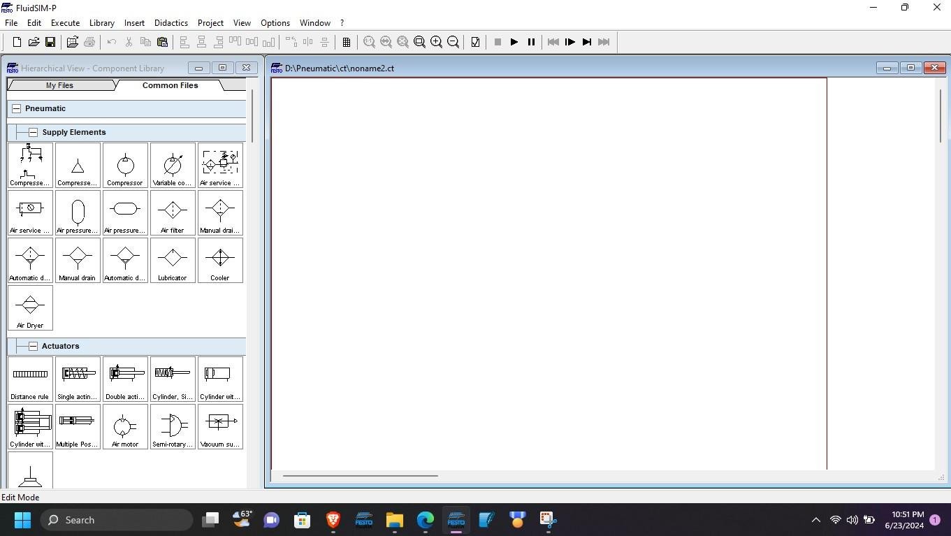
Figure 1. FluidSIM software opens, showing the component library (left) and work area bordered by a red line.
For this example, we are going to implement reciprocating motion of a double-acting cylinder. To add a component like a double-acting cylinder to the design area, the specific cylinder is first sourced in the component library (‘actuator’ section), then once found, dragged onto the design window. The same approach can be taken to add the solenoid-operated 5/2 DCV and the compressor from the supply elements list.
Once you have all the components placed, join the circular nodes representing the connection points to complete the circuit. Port 4 on the DCV is connected to the extension port of the double-acting cylinder while port 2 is connected to the cylinder retraction port. Port 1 is connected to the compressor. Finally, ports 3 and 5 are the exhaust ports of the DCV, and they open to the atmosphere.
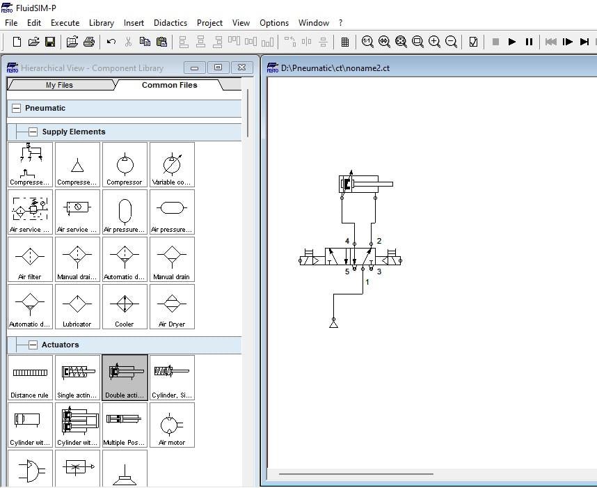
Figure 2. The final airflow circuit after components placement and pneumatic connections.
Implementing the Sensor and the Electrical Circuit
With our pneumatic circuit complete, we can now add the electrical components for the sample project: the power supply, the magnetic proximity switch and manually operated push button found under switches, and two solenoid valves under relay components. The electrical and sensor components can be connected as shown in Figure 3 below.
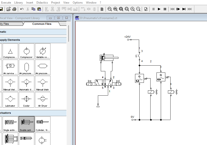
Figure 3. Pneumatic circuit and the electrical circuit with two proximity switches and two solenoid valves.
Adding Labels to the Diagram
To complete our electro-pneumatic circuit, we need to add actuating labels to identify the function of the components in the circuit in relation to the pneumatic system. First, we need to add the actuating labels of the proximity switches on the double-acting cylinder by right-clicking on the cylinder and navigating to properties.
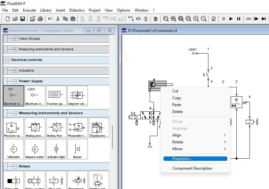
Figure 4. Click on properties to open the cylinder configuration window.
After navigating to the actuating labels, we can add the label for the proximity switches as SQ1 and SQ2 while also configuring the position of placement on the cylinder relative to the cylinder’s maximum stroke. For this example tutorial, the maximum stroke is 100 mm.
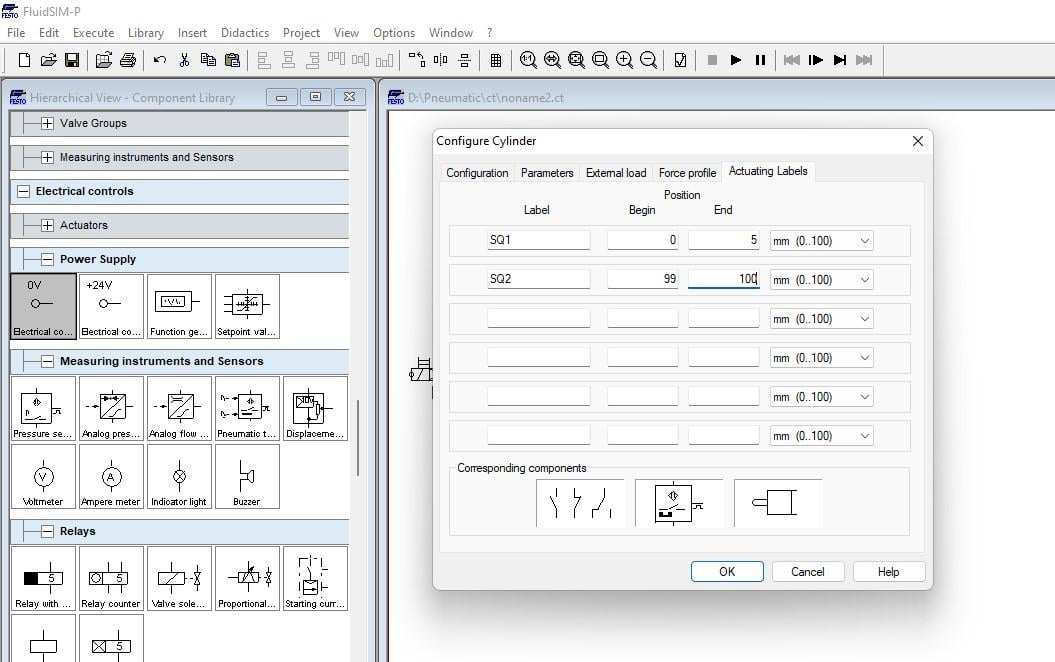
Figure 5. Adding actuating labels for the magnetic proximity switches and defining their position on the cylinder.
To associate the label placement with the proximity switches in the electrical connections, we can right-click on the switch and click on properties to open the pop-up window to add the label as shown below. Do the same for the other switch and add SQ2 as the label.
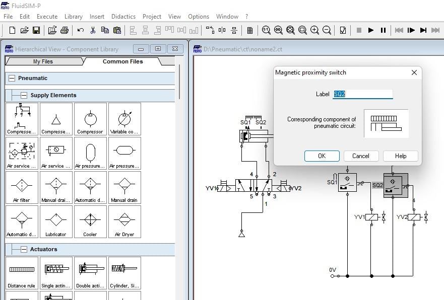
Figure 6. Adding labels to the proximity switches.
When it comes to adding labels to the solenoid valves, the circular node on the solenoid highlighted green on the DCV figure below, is right-clicked and the label property is added to both solenoids. For this example, the labels used are YV1 and YV2.
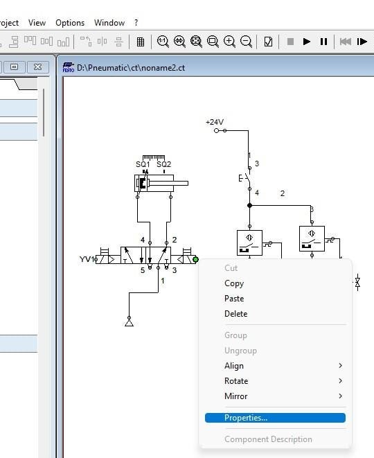
Figure 7. Add the label property for the DCV.
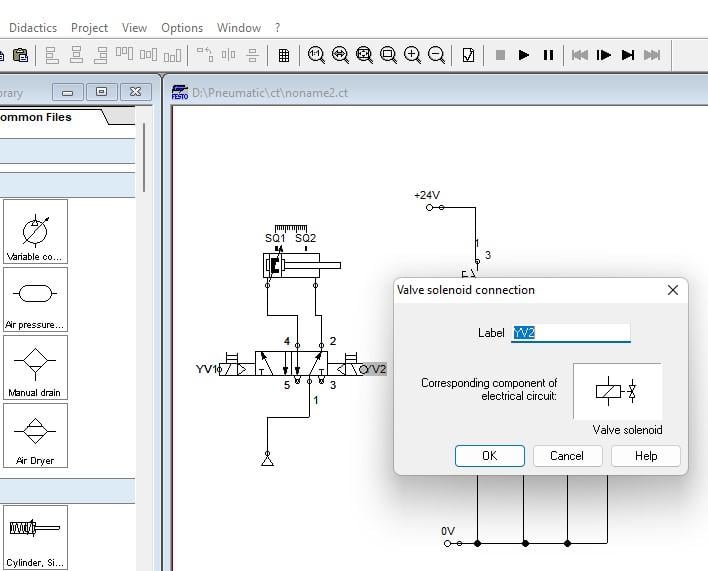
Figure 8. Add the solenoid valve connection label as YV1 and YV2 after clicking on properties.
Once the labels are assigned to the DCV, the label placement can then be associated with the solenoid valve connection in the electrical circuit by navigating to properties and adding the label. Keep in mind that SQ1 actuates YV1 whereas SQ2 actuates YV2.
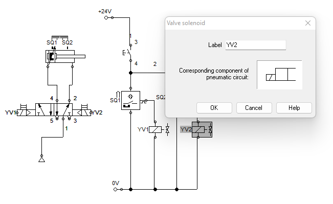
Figure 9. Adding labels to the solenoid valves in the electrical circuit.
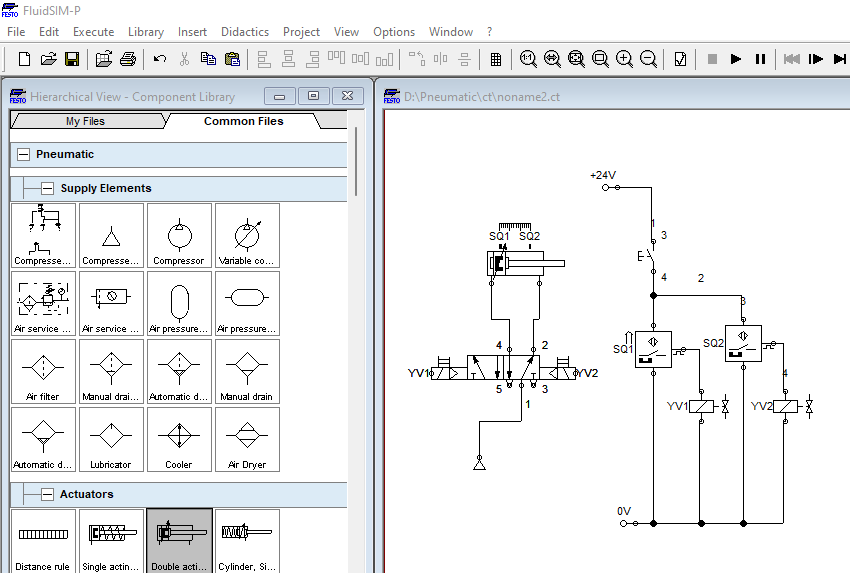
Figure 10. Final electro-pneumatic circuit after addition of all labels.
Simulation of the Electro-Pneumatic Circuit Design
From the sample circuit implemented, the expected results are that when the pushbutton is pressed, power flows through the proximity switches SQ1 and SQ2, and based on the position of the cylinder, the switches SQ1 powers solenoid YV1 while SQ2 provides a signal for solenoid YV2. To simulate the final electro-pneumatic circuit, click on the play icon in the toolbar at the top.
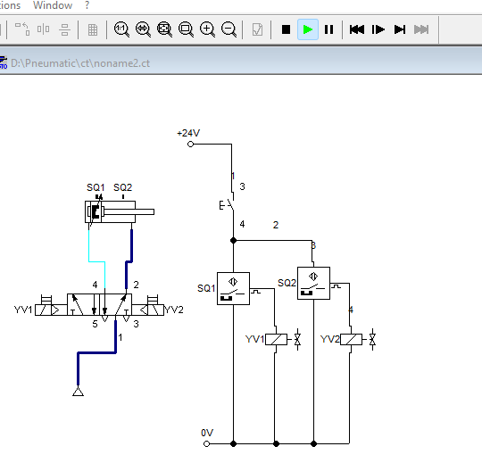
Figure 11. Pneumatic circuit after starting simulation where the navy-blue color represents the flow path of air.
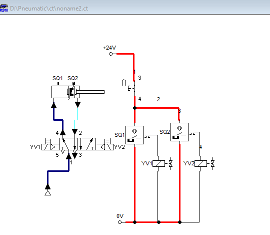
Figure 12. The circuit after clicking on the push button, shows the power and air flow in the system.
The pneumatic system reciprocates when the power is switched on as shown in the simulation images below.
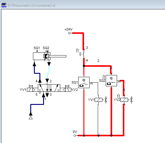
Figure 13. Cylinder extension triggers SQ2 which powers YV2 to extend the cylinder.
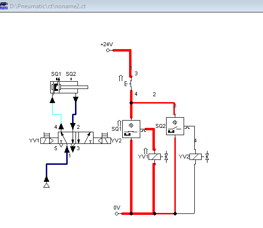
Figure 14. The cylinder retracted triggers SQ1 which powers YV1 to extend the cylinder.
Designing and Simulating Complex Electro-Pneumatic Circuits
Designing and simulating electro-pneumatic circuits for complex systems often involves the use of a wide range of components. Despite the challenge of learning a new concept, this tutorial offers the basic concept and with constant practice and exploration, handling complex circuit design can be simple.
One of the aspects you can explore is the simulation of electro-pneumatic systems using GRAFCET I/O available in Festo’s FluidSIM software.
Copyright Statement: The content of this website is intended for personal learning purposes only. If it infringes upon your copyright, please contact us for removal. Email: admin@eleok.com