Learn how to set up Ethernet/IP communications, including steps for both the FANUC controller and the Studio 5000 environment for a Rockwell PLC.
Connecting a PLC to a FANUC robot via Ethernet/IP offers numerous benefits for industrial automation. It gives access to integrated control, allowing coordination between different manufacturing process components.
The PLC can send commands to the robot through standardized data exchange and receive real-time status updates, a feature that significantly enhances monitoring and control capabilities. Ethernet/IP’s widespread use ensures easy integration with other devices on the factory floor, giving you confidence in the system’s compatibility and scalability.
Required Controller Options for Ethernet/IP Communication
FANUC robots must be equipped with an Ethernet/IP communication option. If your standard robot installation doesn’t have this feature, you should contact FANUC for guidance and information on the process and costs of adding this feature to your robot system.
- Ethernet Global Data (EGD) IO (R793): This option allows your robot to exchange input/output data over Ethernet with other robots, eliminating the need for a PLC (Programmable Logic Controller). It simplifies connectivity by directly linking robots.
- Ethernet/IP Adapter (RTL-R784): With this setting, the robot acts as a slave device within a PLC-controlled network. It communicates using a specific IP address, allowing it to receive instructions and send information through the network.
- Ethernet/IP Scanner: Includes Adapter (RTL-R785): In this configuration, the robot serves as the master device on a network of slave devices. This allows the robot to control and coordinate the network activities.
- Ethernet Safety: Requires Adapter (RTL-R713): This feature enables the robot to safely exchange input/output with a safety PLC, like Rockwell GuardLogix or Compact GuardLogix. It allows safety signals to be managed over Ethernet/IP, reducing the need for traditional wiring safety measures in the work cell.
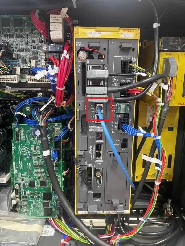
Figure 1. The location of the Ethernet Plug:1 within the R30iA/B controller.
Setup Host Communication: FANUC Teach Pendant (R30iA/B Controller)
The robot’s host communication settings must be configured to ensure proper communication through the Ethernet network.
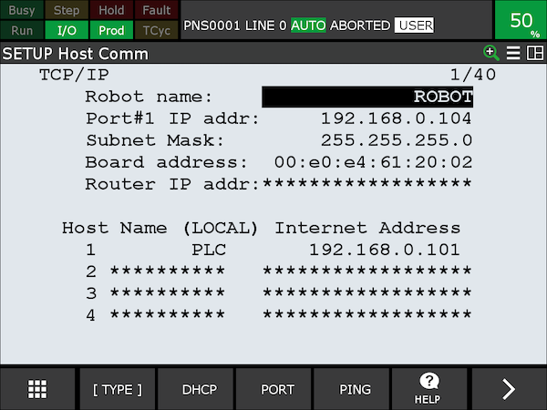
Figure 2. Host Comm Setup: Menu > Setup > Host Comm > F3 for (Port), and then choose either port 1 or 2, depending on where you plugged in the Ethernet cable.
To set up the host communication, follow these steps:
- Navigate to the host comm setup page.
- Change the IP address for Port #1 or Port #2 as necessary. It’s usual to set the IP address to almost match that of the PLC, differing only by the last number (octet) in the address.
- Click the right arrow in the bottom right corner to find the initialize button.
- Press the INIT button on the port to establish a connection.
- Under “Host Name (Local) Internet Address,” name your PLC and enter its IP address.
- Press the INIT button again while the “PLC Host” is highlighted. Again, initializing ensures everything is connected correctly.
- The “PING” feature can verify a successful connection.
- Cycle power through the teach pendant or robot controller to finalize the changes.
Ethernet I/O Setup: FANUC Teach Pendant
In the Ethernet/IP adapter screen, you must specify the I/O size, measured in 16-bit word sizes. For example, if you require 32 bits for input and output, you would set the size to 2 words each. By default, the adapter connection is configured for four words (64 bits) each for inputs and outputs. Any changes to the I/O size will require you to restart the robot before the changes take effect.
Note: The I/O size set on the robot controller must match what is specified in the PLC device setup; this will be important when setting up the PLC Ethernet communications.
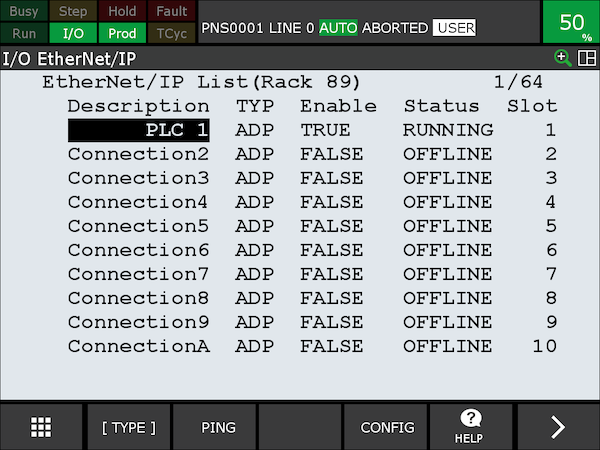
Figure 3. Ethernet/IP List Screen. ‘TRUE’ indicates that the PLC is enabled and operational.
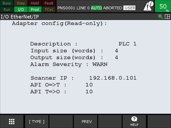
Figure 4. Ethernet/IP Adapter screen.
The instructions for navigating to the Ethernet/IP adapter screen and setup are below.
- Press (MENU)
- Select (I/O)
- Choose (ETHERNET/IP)
- Press (ENTER)
- Use the cursor to navigate to the “ENABLE” column and turn on the adapter by pressing (TRUE) with an (F) command button. If you plan on changing the needed words, press (FALSE), modify the words, and then change it back to (TRUE).
- Select enter the desired connection number in the description column (the adapter connection we selected is [1]). Then, press (CONFIG).
- Enter your required input and output sizes.
- Lastly, restart the robot to apply the changes with [FCTN] > [CYCLE START].
I/O Configuration: FANUC Teach Pendant
Using a FANUC teach pendant to configure I/O settings when setting up Ethernet/IP allows you to manage and monitor the I/O data the robot controller exchanges with a PLC. This includes enabling and configuring the I/O data, setting up communication parameters, and ensuring that the robot can effectively send and receive signals to control operations and respond to changes promptly. It’s about creating a communication pathway so the robot system integrates smoothly with the rest of the manufacturing or processing environment, through the PLC.
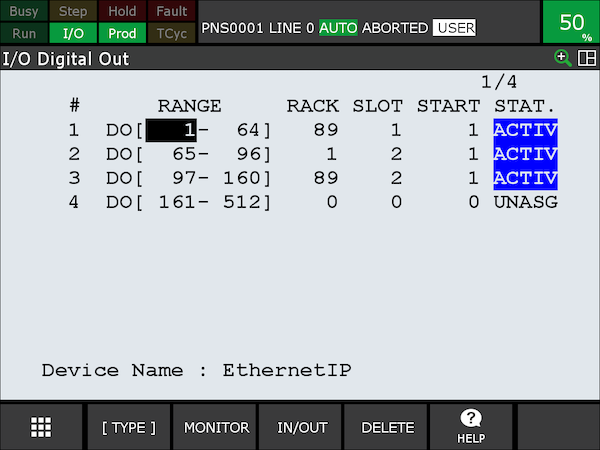
Figure 5. Navigate through Menu > I/O > Digital > Config to reach this screen.
Setting up the digital outputs is straightforward. Simply select the range of I/O you need. For example, if you need to use outputs 1-64, then map them accordingly within that range. The designated rack number for Ethernet/IP is “89”. With only one robot arm connected to the controller through a single adapter in slot one and aiming to access digital output 1, set the start position to 1.
Following the modifications, the STATUS of the adjusted outputs has shifted to PENDING. Restart the robot controller to activate these changes using the FCTN button.
UI and UO (UOP Signals) Configuration: FANUC Teach Pendant
UOP signals serve as the vital link for communication and coordination between FANUC robots and external devices like PLCs. These signals can provide functionalities like starting, stopping, and controlling robot programs directly through a PLC controller. These signals are configured similarly to digital outputs and serve specific functions assigned to each signal type. They are already labeled and tasked with specific roles.
To make a long story short, you will use these signals to start the robotic program from a PLC/ HMI. For future reference, [IMSTP], [HOLD], and [SFSPD] must be enabled to start a program.
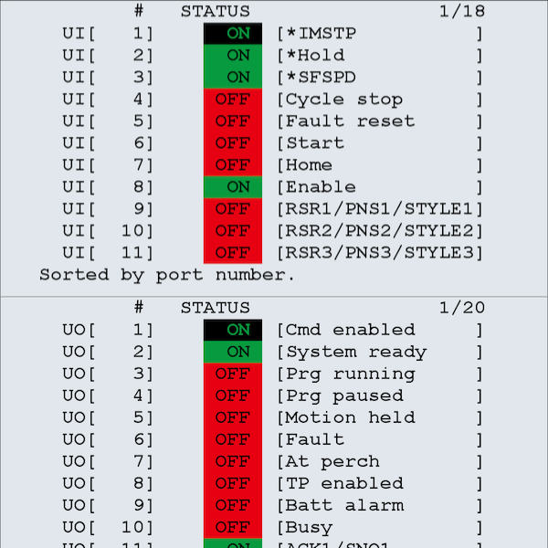
Figure 6. Navigate through I/O > Type > UOP (IN/OUT) to reach these screens.
Enabling the I/O Signals
Now that the signals have been mapped and their functions understood, we need to activate them.
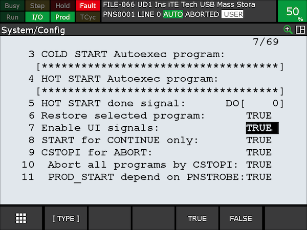
Figure 7. Enable UI signals: menu > system > config.
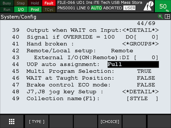
Figure 8. UOP auto assignment: menu > system > config.
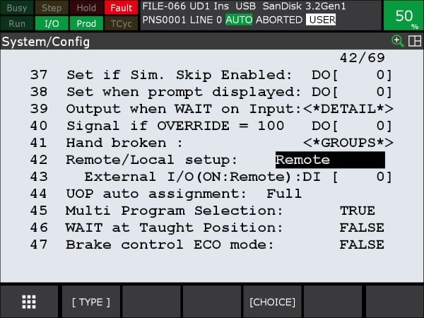
Figure 9. Remote/local setup: menu > system > config.
First, we need to enable the UI signals to allow communication between the PLC and the robot through these signals. For setting #44, remember that the external signals (UI [1 to 18]) are turned off when the value is set to FALSE. This value should be switched to FULL to allow programs to be initiated by the PLC. Lastly, on line #42, change [LOCAL] to [REMOTE] to complete communication with the PLC.
PLC Communication: Studio 5000 Logix Designer
On the PLC side, the setup is fairly straightforward. We’ll configure a generic Ethernet module via the “A1, Ethernet” tab. The accuracy of this setup is crucial, as any errors in data entry could prevent communication between the robot and the PLC.
Begin by entering the robot’s correct IP address. Then, under connection parameters, ensure the assembly instance information matches; Input: 101, Output: 151, and Configuration: 100. The input and output can vary between different robotic controllers or different ports: see the robot manual for further instructions. The size should always correspond to the number of words you configured for your robot earlier in this tutorial (remember, we used 64 bits, which is 4x 16-bit words), and keep the configuration size at zero.
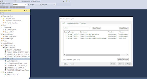
Figure 10. Locating the “Generic Ethernet Module.”
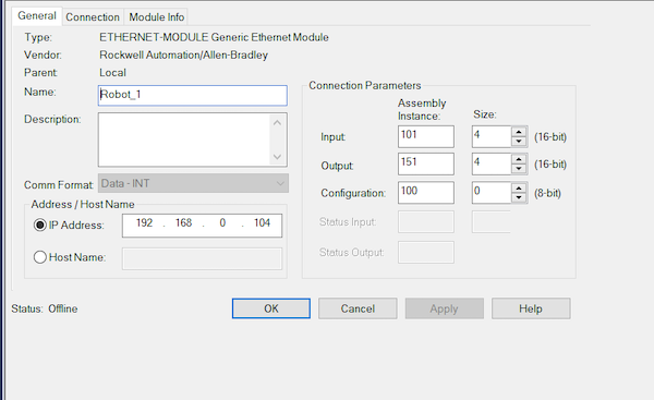
Figure 11. Configuration of the robot module Ethernet device. Ensure that the assembly instances are input correctly and that the sizes align with the settings previously input into your teach pendant.
Checking Ethernet Communication Through I/O Monitoring
We will manually activate an output signal on the robot’s teach pendant and then check if this change is reflected in the PLC for the robot’s inputs. Remember, the robot’s digital output on the teach pendant is correlated to a robotic input signal on the PLC.
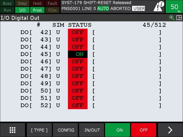
Figure 12. Digital output [45] is manually forced on for testing.
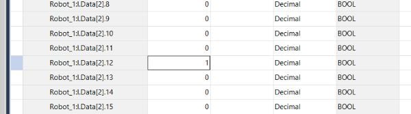
Figure 13. While the robot output is forced on, the PLC input shows successful communication.
Copyright Statement: The content of this website is intended for personal learning purposes only. If it infringes upon your copyright, please contact us for removal. Email: admin@eleok.com