Learn how to use an AutomationDirect BRX PLC with the Do-more Designer software. This tutorial will cover discrete I/O commands along with basic timing and counting ladder functions.
These days, it’s not always accurate to assume that a bigger computer means that’s always better. The same is true for PLCs. As electronics technology has improved, the size of durable, industrial machines continues to shrink. Additionally, the increased processing ability allows the PLC to be the central communication hub. This means that the PLC itself doesn’t need to contain all of the local I/O, instead relying on fast networking protocols to communicate with remote I/O blocks on each machine.
The BRX PLC from AutomationDirect combines all of the normal functions we expect in a PLC with the IIoT functions that allow data links with remote services, namely MQTT for cloud data and SMTP for email and text messaging.
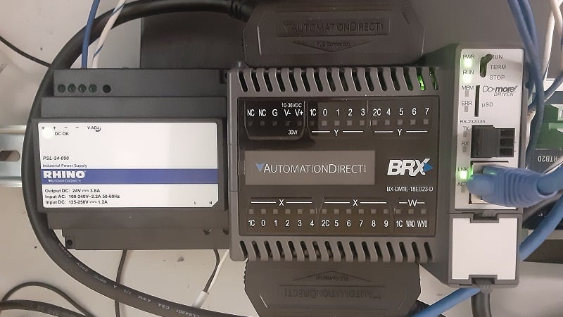
Figure 1. The hardware arrangement consists of the power supply and PLC. One pushbutton is used for the input.
In this tutorial, we will cover the initial connection and software overview, culminating with the typical contact (input) and coil (output) instructions, perfect for a foundational understanding of the platform.
BRX Hardware Arrangement
This benchtop setup includes a BRX CPU of the DM1E series, which means it has both a serial RS-232/485 and an Ethernet port. Our connection method will be Ethernet.
This CPU includes embedded I/O with 10x AC or DC inputs, which can be sinking or sourcing. There are 8x DC sourcing outputs. This CPU also includes 1x analog in and 1x analog out, both of which can be configured for voltage or current with various industry standard levels.
The unit only requires a DC power supply in addition to the PLC and one standard pushbutton has been connected to the first input, terminal X0. To complete the circuit, 1C, the common of the input terminals, has been connected to -V of the power supply.
Note: On many brick-style PLCs, the inputs are on the top, while the outputs are on the bottom (examples include the S7-1200 and MicroLogix). The BRX is opposite, with the inputs (X0-X9) on the bottom and the inputs (Y0-Y7) on the top. Do not connect pushbuttons to an output or a short-circuit will result. For this reason, please try to use a power supply with overcurrent shutoff protection.
Go ahead; ask me how I found out about this.
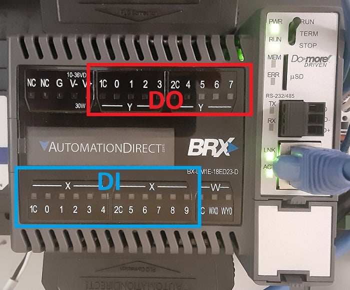
Figure 2. DI and DO connection points.
Installing the Do-More Designer Software
The BRX PLCs are programmed with the Do-more Designer software, version 2 or later. The current version at the time of writing is 2.9.4.
Download and install the software, then open it. You may be prompted to download the most recent firmware revisions for the PLC, and if you are programming a fresh PLC on a bench test unit, this is a good idea. Never update firmware on an active production machine unless it is fully backed up or you are absolutely assured that it will not erase any important programs or settings.
Our plan of action for this project is to make the initial connection to the PLC over Ethernet, then update the firmware, and, finally, design and download a working program.
Connecting to the BRX PLC
This software has a smart interface for connections, unlike many that I have experienced. Connect the Ethernet cable to the PLC and the PC, then open the software. Create a “New Offline Project” and select your model of CPU.
After the project opens, go to the PLC top menu and select Connect. A PLC should appear in the list, uninitialized with an IP address of 255.255.255.255.
At this point, if you do not see a PLC in the list, verify that the PLC is powered up and the Ethernet cable is connected. Your PC must have an activated Ethernet port.
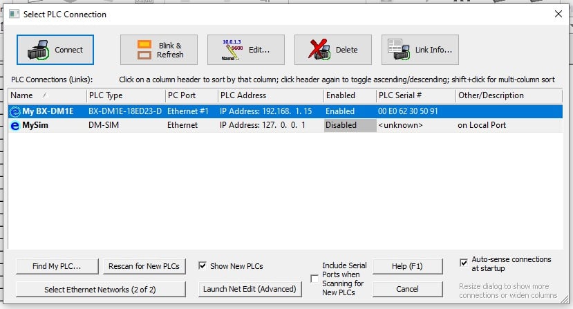
Figure 3. Locating the correct PLC from the Connection menu.
When you “Connect,” the IP address must be set. At the top, I called this a smarter process than others. The Do-more software scans your Ethernet interface to determine your IP and subnet, then auto-fills a recommended IP address to match. You can accept this one, or select a different one. You don’t even need to open the network configuration settings on your computer to set up this PLC!
You should now be successfully connected.
Loading Firmware
To ensure the latest version of firmware, go to the PLC menu and select Update Firmware…
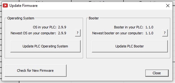
Figure 4. Updating OS and Booter firmware.
You can update the PLC OS and the Bootloader, but BE SURE to never disconnect power or communication during a firmware update.
Designing a Ladder Program
The Main ladder routine is the default cyclic task for our programming to be installed. The commands are accessed via the ‘Instruction Toolbox’ on the right side of the screen. If the instructions are not visible, press the ‘Edit’ button near the top to toggle the Toolbox on or off.
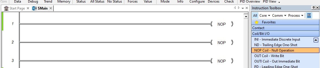
Figure 5. The Instruction Toolbox on the right side.
By default, each ladder rung ends with the NOP command. There are 10 blank rungs, reminiscent of AutomationDirect’s other products, DirectSoft and Productivity Suite.
We want to drag one Normally Open (NO) Coil to the left end of the first rung and type in the address of X0 (or whichever terminal you installed the button). A simple OUT coil should be dragged to the right end. This will be given the Y0 output address.
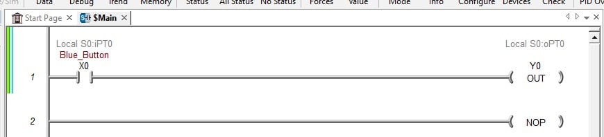
Figure 6. A completed single-line program.
To download, first ‘Check’ the program with the green checkmark button, then press ‘Write PLC.’
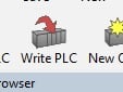
Figure 7. The Write PLC button.
If the program does not execute, press the Mode (traffic light) button to ensure that the PLC is in RUN mode. If not, make sure the physical switch on the PLC is set to TERM, then use the Mode settings to switch to RUN from the software. You can leave the PLC in TERM mode while programming.
Naming Variables
Using X0 and Y0 is effective, but not for a large program. We need to provide logical nicknames for variables.
Press the Dashboard button near the top, then click on the DI terminal bank -> Edit I/O Documentation.
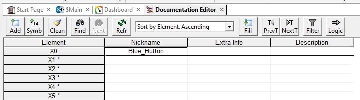
Figure 8. ‘Edit I/O Documentation’ menu to choose logical device names.
You can provide nicknames and descriptions for each terminal as needed.
Timers and Counters
For some extra slightly advanced work, we can configure timers. The typical on-delay timer is given the abbreviation ONDTMR, found inside the Timer/Counter/Drum menu in the Instruction Toolbox.
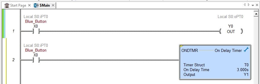
Figure 9. This timer, energized by X0, has been configured for 3.000 seconds with an output of Y1.
It is quite simple to use a timer. It exists as an output on a run with various conditions to energize it. The output bit energizes when the time is reached. This bit can be an output or a memory coil (C bits).
Counters are very similar, but they must include a bit to serve as the reset instruction.
BRX PLC Introduction
This article is only a brief intro to the BRX PLC family. Future articles will provide guidance on accessing the analog, MQTT, SMTP, and other communication functions.
Happy programming!
Copyright Statement: The content of this website is intended for personal learning purposes only. If it infringes upon your copyright, please contact us for removal. Email: admin@eleok.com