Sensor networks with built-in logic functions can save cost and program execution speed, but what are those various logic functions, and when might they be preferred over normal PLC ladder logic?
The logic functions that exist within some sensors are fundamental operations that process input signals to determine an output. These functions help the sensor make decisions by applying rules such as AND, OR, XOR, or gated latches/flip-flops.
This allows sensors to react or trigger actions based on specific conditions without requiring a central processor to interpret the data. Logic functions enable sensors to combine, modify, and analyze incoming data to produce a helpful output based on predefined criteria.
Most sensors do not have logic functionality integrated into them. These logic functions appear most commonly in sensors with configurable protocols, IO-Link being one of the typical examples. IO-Link software configuration allows multiple signal ranges to be simultaneously compared, and the final output sent to the controller meets a comparison condition, providing window or toggling functions.
Logic Function Sensors vs. a PLC
While PLCs are incredibly versatile and widely used in industrial automation, there are scenarios where a PLC may not be the best choice to directly handle logic functions.
Simple Automation Applications
If your automation needs are relatively straightforward and minimally complex, using dedicated sensors with built-in logic functions may be more efficient than deploying larger PLC systems. For instance, if you only need to monitor a few inputs and activate basic outputs based on predefined conditions, using sensors with integrated logic could allow much simpler programming.
Cost Considerations
PLCs may require a significant hardware, software, and maintenance investment. Using sensors with embedded logic functions can offer a more cost-effective solution without compromising performance for budget-constrained projects.
Program Execution Speed
Each step in a PLC program adds to the overall cycle time. For these simple logic comparisons, lines of code can be reduced by performing the logic calculations directly on the sensor.
Common Logic Functions
AND
This function utilizes an AND gate in digital circuits. An AND gate is a fundamental digital logic gate that generates a true output (1) only when all its inputs are true. This feature is essential in industrial controls, where machinery functioning may rely on multiple safety conditions being met simultaneously. Using AND gates guarantees that all specified conditions are fulfilled before receiving an input signal.
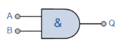
Figure 1. This image illustrates an “AND” logic symbol. “A” and “B” inputs must both be active to energize the “Q” output signal.
OR
The “OR” logic function is a fundamental operation in digital logic. Its output is true if at least one of the inputs is true. You can imagine it as a decision gate that opens if any of the specified input signals indicate a “true” state. For example, in a simple scenario with two inputs, A and B, the OR gate output will be true if either A or B (or both) is true. This function is commonly used in circuits to model scenarios where multiple conditions can lead to a single outcome, providing reliability in systems that respond to various input combinations.
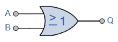
Figure 2. This image shows the “OR” logic function. If either “A” or “B” receives an active signal, “Q” will also give a signal.
XOR
The “XOR” (Exclusive OR) logic function is a fundamental operation in digital logic. The output is true if exactly one of the inputs is true. In other words, the output is true if the inputs are different; if both are the same, the output is false. Think of it as a gate that allows passage only if one input is true but not both. For example, if input A is true and input B is false, or if input A is false and input B is true, the output of the XOR gate will be true. However, if both inputs are the same (both true or both false), the output will be false. XOR gates are commonly used in various applications, including error detection and signal processing, where distinguishing between input states is necessary.

Figure 3. An image of the “XOR” logic symbol.
Gated SR-FF
A gated set-reset flip-flop can be compared to a room with two buttons on the wall: one to turn on the lights (the set button) and one to turn them off (the reset button). However, this room also has a unique switch by the door (the gating switch). When the gating switch is on, pressing the set or reset button immediately affects the lights. But if the gating switch is turned off, the set and reset buttons won’t affect the lights until the gating switch is turned back on.
This arrangement allows for precise control over when the set and reset actions take effect, adding a layer of flexibility to managing the state of the lights. In digital circuits, this concept is used to control when certain operations occur, enabling precise timing and coordination of actions.
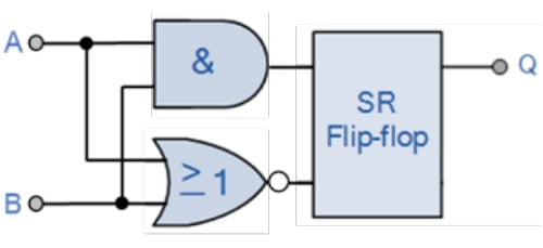
Figure 4. A digital circuit reference to the “gated SR-FF” function.
Application Examples for Logic Function Sensors
Environmental Monitoring in Cleanroom
Maintaining optimal product quality and preventing contamination is crucial in a cleanroom environment. Sensors equipped with temperature and dust detection capabilities can be deployed with the OR function to trigger an alarm if the temperature exceeds a predefined threshold or the dust level surpasses a specific limit. This approach ensures swift notification of potential environmental hazards, enabling timely interventions to maintain the integrity of the controlled environment and uphold quality standards.
Automated Inspection
Maintaining part quality is important in automated manufacturing to meet industry standards and customer expectations. Sensors with temperature and vision detection capabilities can be vital in defect detection. Using an OR function, these sensors could trigger alerts if the part’s temperature surpasses a predefined threshold, causing deformities, OR if visual anomalies are detected during inspection.
Using PLCs and Logic Function Sensors
Combining PLCs and sensors with integrated logic functions can also be a great choice. These sensors help reduce wiring complexity for the PLC, simplifying the setup and minimizing potential points of failure. Additionally, since the sensors handle basic input processing, the workload on the PLC is reduced, allowing programmers to focus on more complex tasks. Also, in space-constrained environments, the compact size of these integrated sensors can be helpful if you don’t have room for two sensors.
Control automation is all about leveraging the strengths of each component to create a robust automation system that meets the specific project requirements.
Copyright Statement: The content of this website is intended for personal learning purposes only. If it infringes upon your copyright, please contact us for removal. Email: admin@eleok.com