Learn how to write a ladder logic program to assign a string value to a data register and share that register with any HMI compatible with Mitsubishi’s MELSEC PLC series.
Human-machine interface (HMI) panels are often designed for the control and display of essential data from the control system to the users. From interaction with password entries to display number values, HMIs can also display text (strings) as an output from a ladder logic program in a PLC. In this tutorial, we are going to explore how we can write a simple ladder logic program in MELSOFT GX Developer that moves strings to a PLC data register for HMI display.
HMI Text Display Ladder Logic Program
In some MELSEC series PLCs, displaying text is made possible with a ladder function that moves Strings to a data register that is later decoded by an HMI panel. To bring out the concept better, we are going to explore an example where a text will display the condition of a light bulb in a simple light-switching operation.
In this sample project, two momentary switches with addresses of X000 and X001 will be used to switch output Y000 (lamp) ON and OFF respectively. When the switch with address X000 is pressed, the text “LIGHT IS ON” is moved to data register 0 (D0) for the real-time status display of the lamp. However, when X001 is pressed, a new text “LIGHT OFF” is moved to D0, thereby changing the text displayed on the HMI.
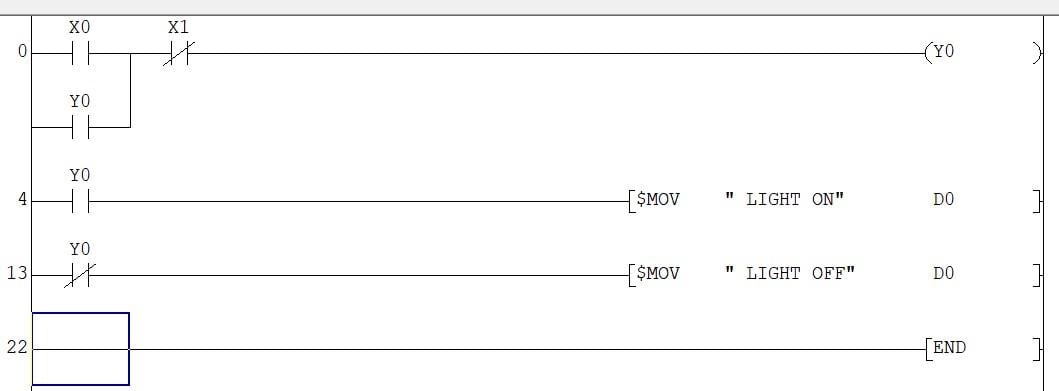
Figure 1. Using MOV commands to populate a character string.
When writing a function to move strings to a data register, a MOV application instruction is selected, or use the keyboard shortcut F8 and carefully note the syntax of the character string transfer command:
–[$MOV Character String (S) Data Register (D)]–
S represents the text to be moved, and D is the address of the data register to where the text is being moved.
GOT HMI Design and Simulation Results
This simple PLC program can work with any MELSEC-compatible HMI like INNOVANCE or Mitsubishi’s GOT 2000 series. To bring our previous example project to life, we are going to use GT Designer and Simulator 3 to simulate the output of our ladder logic program. Of course, if you have access to an actual HMI, that can be used in place of the simulation.
Launch GT Designer and use the wizard to set up a new project. For the GOT HMI series, we are using the GOT 2000 and MELSEC Q series controllers for this example. Once the setup is complete, we can jump straight to design. Under the object tab, add two switches, setting them as momentary bit switches, and also add a bit lamp, with appropriate addresses for each.
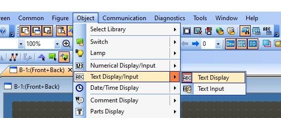
Figure 2. Adding a text display object.
For the text display, add a text display box, also found under the object tab, and set the address to D0. The number of characters to be displayed can also be increased.
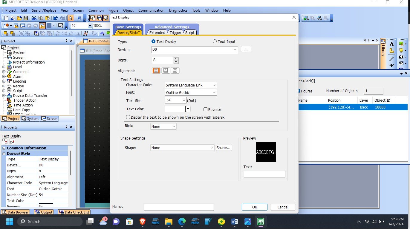
Figure 3. Configuring the text display object with the device address and character count.
To better differentiate the switches, add the style color green for X000 and red for X001 for ON and OFF functionalities. The final design is represented in the image below.
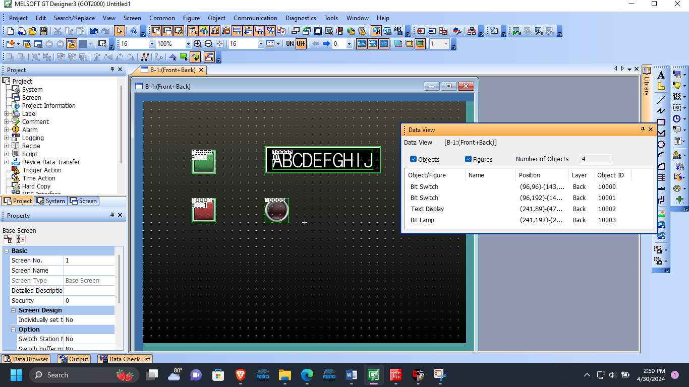
Figure 4. Final HMI Design and a data view table indicating all the objects placed on the base screen.
With the screen design complete, the program can be tested using GX Simulator and GT Simulator 3. This is done by launching both simulators and clicking on the switches to see the resultant outputs relating to the earlier written PLC program.
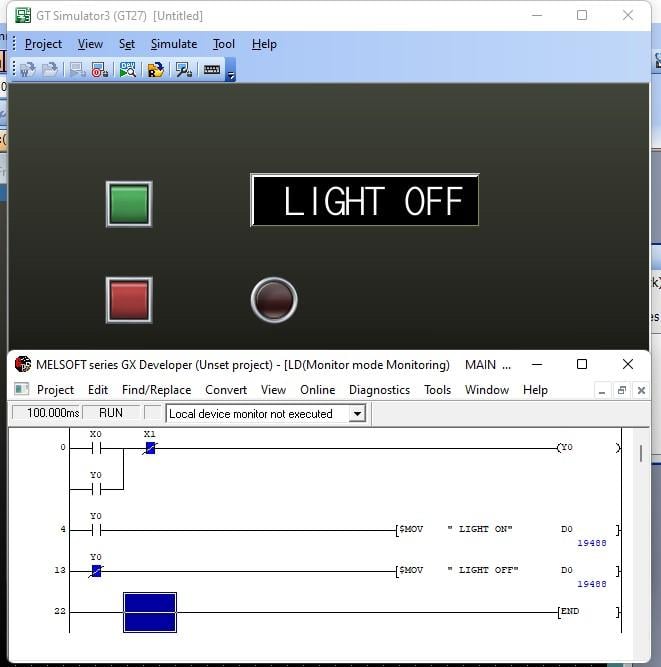
Figure 5. The string “LIGHT OFF” is moved to D0 when the red button is clicked or when the lamp is OFF.
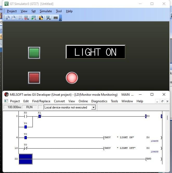
Figure 6. The string “LIGHT ON” is moved to D0 when the green button is clicked or when the lamp is ON.
Why Display Text on an HMI?
Learning how to handle text output in HMIs is important as it can be used to display critical information in an automated system. This tutorial provides an introductory overview of the concept with the light status display. However, there are more use cases like displaying alarms and warnings after conditional inputs like high or low-temperature readings. The text can also work as an input for setting text-based parameters and even user prompt passwords.
To grow your programming skills, always attempt to explore more application scenarios. If possible, try to use a range of compatible HMIs since these concepts cut across different models.
Copyright Statement: The content of this website is intended for personal learning purposes only. If it infringes upon your copyright, please contact us for removal. Email: admin@eleok.com