This article discusses PLC Sequencer Logic and the steps needed to accomplish PLC sequencing.
PLCs have a set of inputs from sensors on which logical, and mathematical operations can be done. The output of the PLC is used to control the operating characteristics of the machine or process to which it is connected.
Industrial PLC system in operation.
For instance, a PLC can be implemented for the automatic filling of a tank. A PLC can be connected to a level sensor, start the pump when the level in the tank drops below a certain threshold, and stop the pump when the water reaches a certain level in the tank. This is a simple instance that does not require a PLC. Similar operations that can be controlled with logical operations on data from input sensors can make use of PLC for automation of the process.
Sequencing
PLCs are widely used for automating industrial processes. Many of the tasks performed will depend on another task. Some tasks can be done only after other tasks have been completed. Let me illustrate this with an everyday task we are familiar with.
Here are the steps to take to drive a car in detail:
Step 1: Unlock the door
Step 2: Open the door and climb into the driver’s seat.
Step 3: Buckle the seatbelt.
Step 4: Insert the key into ignition and turn it to start the engine.
Step 5: Release the parking brake.
Step 6: Change the gear to Drive.
Step 7: Press on the accelerator to move the car forward and brake pedal to slow down or stop the car.
These are the steps that need to be done to operate a car. You cannot drive the car without starting the engine or opening the doors of the car. The steps must be done in a certain sequence to operate the car. Similarly, in industrial operations, some tasks need to be done in sequence to achieve the desired outcome.
Sequencing is simply the requirement that some actions or process must be done after a predetermined set of actions have been completed to obtain the desired outcome.
PLC Sequencer
PLC sequencing repeats a set of processes in a certain order until no additional input signals are registered. It is widely used in industrial automation scenarios, specifically in batch operations. The same set of processes is repeated in the same sequence for each new batch.
This is better understood with an example. Imagine there are 4 light bulbs L1, L2, L3, and L4 which are to be turned on in a certain order.
Step 1: L1 and L2 are turned on.
Step 2: L3 and L4 are turned on.
Step 3: L1 and L3 are turned on.
Step 4: L2 and L4 are turned on.
After the four steps are completed, step one is executed, and it goes on. This can be achieved with sequence output instruction (SQO) using a PLC. SQO instruction transfers a 16-bit data to control outputs for sequential machine operations. The symbol for the sequencer output command is as shown below.
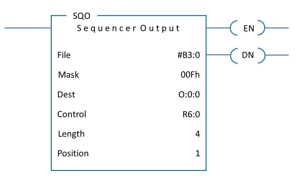
SQO representative symbol.
There are six parameters represented in the symbol.
File: This represents the memory address of the sequencer file. We must create a file with Boolean bits representing the various steps in the sequential output.
Mask: It represents the address in which the sequence instructions are given. In the example symbol given we have given 00F in hexadecimal. The first eight bits do not provide any data and the complete data is in the last four bits.
Dest: This is the address of the output file to which data is transferred from the sequencer file.
Control: This shows the address of the control element that stores status byte., length, and position of the file.
Length: This indicates the number of steps in a sequence. Since we have four steps it is shown as 4 in the symbol.
Position: This represents the exact step that is being executed at the moment.
We also must give the input for the sequencer in the file B3. For example, considering the lights we have, 4 steps, and the file would look like this.
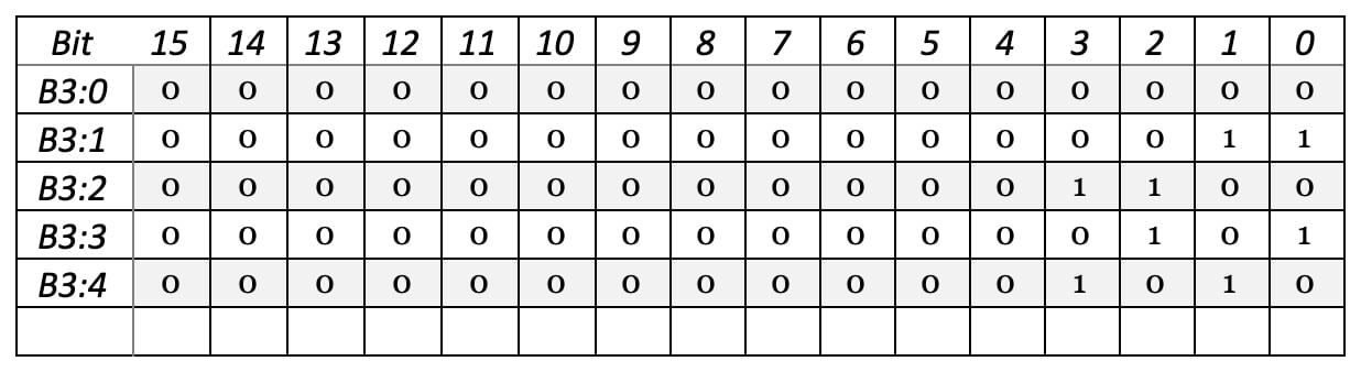
B3:0 represents the starting position of the setup. B3:1 represents the first step and so on. Bit 0 is for the status of L1, Bit 1 for L2, Bit 2 for L3, and Bit 4 for L4. The high value of the bit (1) indicates light being bright, and low value (0) indicates the light turned off. We have mapped the required Boolean values in each step to the sequencer file. The ladder diagram for the setup will be as shown below.
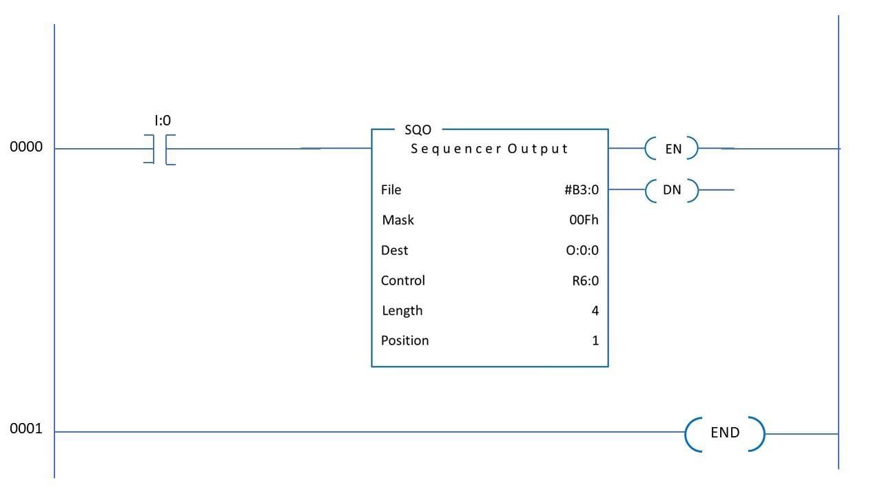
Ladder diagram for the example setup.
The four outputs corresponding to bit 0, bit 1, bit 2, and bit 3 is connected to L1, L2, L3, and L4 respectively. In the initial position, the values in B3:0 will be replicated, and all the lights will be turned off. When the first pulse is applied to I0, B3:1 will be replicated. L1 and L2 corresponding to bit 0 and bit 1 will be turned on.
Similarly, in the next pulse, L3 and L4 will be turned on and L1 and L2 will be turned off. In the next pulse, L4 will be turned off and L3 and L1 will be bright. In the same fashion step, 4 is replicated at the next pulse of I0. After that step 1 will be replicated again.
The IO in this example can be a switch that needs to be turned on manually or output of a sensor which measures some parameters. Instead of the light bulbs, the output can be a crane or motor or other industrial equipment.
This is how PLC sequencing works. In most cases instead of sequencing, timers, or counters can be used to implement the same operations. SQO takes much less memory space compared to other methods.
Copyright Statement: The content of this website is intended for personal learning purposes only. If it infringes upon your copyright, please contact us for removal. Email: admin@eleok.com