There are multiple methods for mapping inputs and outputs to an industrial robot. In this article, we cover two of the most popular methods: letting the robot or the PLC control the I/O signals.
There is one unavoidable question to ask during your next robotic design, no matter what brand of robot is used: you need to determine and implement some amount of inputs and outputs to control the operation and the end effector of the robot.
These end effector functions could be a welding torch, adhesive dispense head, or a pneumatic gripper. The inputs and outputs allow the robot to perform work in the physical world. In the past, robots needed to be ordered with discrete input and output cards installed in the robot controller, but today, the functionality is almost always built right in. However, we still need to configure the communication for our external network.
Robot I/O Signals
Any communication to the robot or the tools on the end effector had to go through hard-wired signals. Today, we have Fieldbus protocols which allow designers to not only send boolean signals but we could also group these signals to form a byte or a word of integer signals. The Fieldbus layout dictates who owns the I/O and how it is interpreted by the receiving device.
In this article, I will go over two different methods that explain how we can add I/O to a robot.

Figure 1. Robot work cells must be able to communicate with end tooling, cell I/O, and the network, as appropriate. Image used courtesy of Unsplash
Fieldbus Layout
Typical Fieldbus technology relies on a single master (controller) device and many nodes (slave devices) on the network. The master device will communicate with and control all the slave devices on the network. When a PLC exists on the network, the PLC is the master. Most of the time, this master/slave topology is configured automatically, but when we want a robot to control its I/O then we need to make sure the robot is the master.
Robot Options
When ordering your robot, there are many options to choose from, so you need to know your expected topology before ordering. One of the many options will certainly be the Fieldbus technology; Ethernet/IP, PROFINET, or EtherCAT are just some examples of the common Fieldbus protocols. Almost across the board, robot manufacturers offer all the popular protocols as options.
After you select your protocol, you will need to know if you want a master/slave adapter (typical network interface card) or a slave adapter (sometimes referred to as a scanner). This decision will depend on whether you are mapping the I/O to the robot or the PLC.
Robot as the I/O Controller
The design of your robot end effector I/O will depend heavily on the company or customer you are working for. Some people have very strong opinions as to who should own the I/O. One method is to order the robot with a master/slave adapter and have the input/output modules mapped directly to the robot.
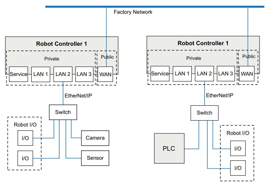
Figure 2. If the robot is the owner of the I/O, all hard-wired or networked I/O for the cell is driven directly by each robot. Image used courtesy of ABB
In this method, the robot is said to ‘own’ the I/O and the PLC will not be aware of any I/O state, except what is explicitly sent over the fieldbus network to the PLC address. Each robot manufacturer has a slightly different method for mapping devices through the Fieldbus technology, but is similar to how you would add devices to a PLC ethernet map.
The scanner will need to have an IP address assigned to it, and each device on the network will also need to have an assigned IP address. The amount of data transmitted between the adapter and the device will also need to be specified. Input and output devices can now be added to the adapter and mapped within the program. An EDS or GDS file can also be uploaded to the robot to make this process easier.
Essentially, we are creating an isolated network between the end effector and the robot. This mini-network can have a different subnet than the rest of the machine which can save on IP address if required.
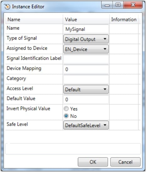
Figure 3. An example I/O signal in ABB robotics software, configuring a digital output on the EN device (an internal Ethernet scanner). Image used courtesy of ABB
PLC as the I/O Controller
Another method is to set the robot as just another node on the same network as the PLC and add the end effector devices to the PLC network. This method requires all the input and output signals to go through the PLC using the selected Fieldbus protocol. A spreadsheet is often used to track the function of each bit in the protocol map. For example, when the ‘gripper closed’ request bit goes HIGH, the logic in the PLC will fire the output to the valve bank on the end effector. This method might seem a little long-winded, but there are some compelling reasons for this strategy.
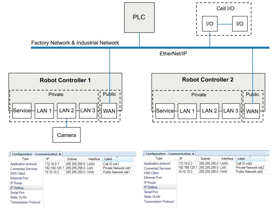
Figure 4. PLC-owner network layout, with the PLC, cell I/O, and robots connected to the same factory network. Image used courtesy of ABB
Where do the Faults Live?
Faults tell operators that something has gone wrong and typically the PLC generates the faults and sends a fault number to the HMI application. If the robot owns the I/O then all the fault logic associated with that I/O needs to reside in the robot code, additional fault numbers need to be generated and sent to the PLC. The common argument is that the PLC generates the faults so the PLC should own the I/O.
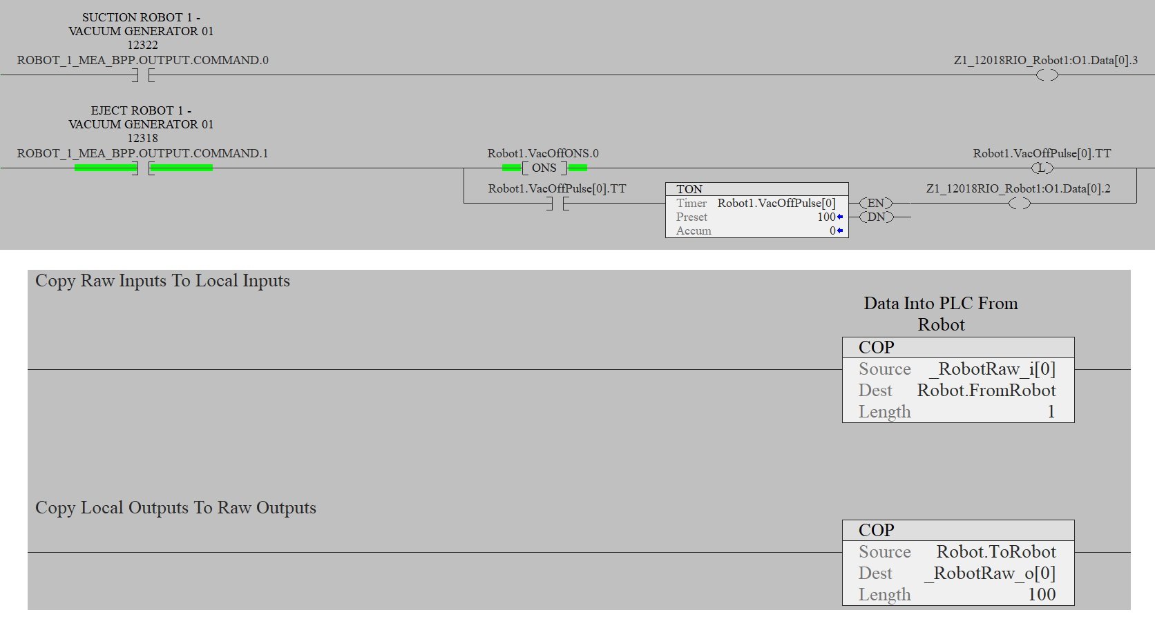
Figure 5. If the PLC owns the I/O, the PLC sends the commands, and then simply informs the robot as to when the I/O signal has reached the destination. Image used courtesy of the author
Scan Time Concerns
A robot controller has a much faster scan time than a PLC, or at least that was the case many years ago. PLC scan time was often slower than the inputs driving the logic. Logic was put in place to slow down the inputs for the scan time of the PLC to catch up.
Today, with quad-core processors, our PLC scan time is often under 2 ms. A common argument for having the robot own the I/O is that the gripper response is faster, given that the robot’s scan time is faster. While this may still be true, the I/O is network based and the network speeds are going to be your deciding factor as to I/O speeds. Fieldbus adapters typically have a 10 to 20 ms refresh rate, so you won’t get a new state for at least 10 ms anyway. In some applications, your end effector will need a high-speed response, and in these rare cases, it might make sense to map the inputs to the robot or use discrete hard-wired inputs.
Program Layout
No matter which method you choose, you might need a different layout for your program structure.
Considering the robot as the I/O owner will require more faults to be generated, so a special override background program will need to be generated, and status bits of the I/O plus the communication of the module will also need to be added. If the PLC owns the I/O, the robot can simply wait for the PLC to report the correct end effector state. Standard faults can be generated and transferred to multiple projects.
Both options have their pros and cons. Your own decision on which method to use will depend on the company, customer, or application that fits your situation. Having the PLC own the I/O requires less robot programming and makes the overall layout easier to understand and faster to implement.
Copyright Statement: The content of this website is intended for personal learning purposes only. If it infringes upon your copyright, please contact us for removal. Email: admin@eleok.com