Power delivered to devices can be changed by raising or lowering the voltage and current. But this method does not always produce intended results. Pulse width modulation (or PWM) can be used to better control variable loads.
What is Pulse Width Modulation?
Load devices are designed to run efficiently and perform their respective tasks when provided with a certain voltage, consuming a particular amount of current. To change the parameters of the load, the voltage can be lowered, but this will often have negative effects, such as decreasing the torque of a motor, or lowering the voltage below the forward bias level of a transistor or LED series. To provide variable control without sacrificing operating ability, a different method was needed.
A PWM, or ‘pulse width modulation’ signal is used to reduce the electrical power supplied to an electrical device by switching the signal on and off at a high frequency. As the relative on-time of the signal increases or decreases, so does the average voltage of the signal. This average voltage provides an equivalent lower power, while still maintaining full voltage for the on-state duration of the pulse. Two key parameters control the PWM signal – the frequency of the switching, and the relative duration of the on-time, called the ‘duty cycle’.

Figure 1. Understanding signals in AC and DC circuits is critical for proper operation of the devices.
PWM Carrier Frequency
The switching speed, or frequency, of the pulse depends on the load device that is using the signal. For an electrical heater or motor, the frequency can be quite slow, perhaps in the tens to hundreds of Hz. But for a solid-state device like a relay or LED, the frequency may need to be much higher – perhaps tens of thousands of hertz. The key determining factor is the response rate of the load device.
PWM Duty Cycle
The duty cycle of a PWM signal is the relative amount of time the signal will be on and is expressed as a percentage. If the duty cycle is 100%, the signal will be on all the time. If it is lowered to 50%, the signal will be on for half of the pulse and off for the other half. When controlling motors or heaters we use the duty cycle to dictate the power. If our PWM controller outputs a voltage of 12 volts DC, then a 50% duty cycle would provide the equivalent of 6 volts DC to power the load.
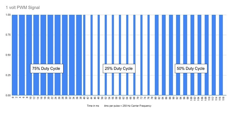
Figure 2. PWM signal showing various duty cycles at a 250 Hz carrier frequency.
PWM for DC Motor Speed Control
DC motor speed and direction are dictated by the voltage applied – change or reverse the polarity of the voltage and the motor will respond in a similar fashion. Voltage can be changed by raising the series resistance within the electrical circuit, which in turn lowers the current through the motor. This change in voltage can be accomplished by series resistors, potentiometers, or rheostats. While these devices may be effective for small changes in voltage, the power and torque of the motor are decreased as the current drops. In addition, significant resistance from these devices can produce a lot of heat which could cause damage to other devices within the electrical system.
A more efficient way to vary voltage is to use a PWM controller. These devices use an analog input converted into a 0-100% duty cycle using the device’s rated voltage. Sometimes these devices will have a fixed input voltage but will drive a solid-state relay allowing the user to provide an auxiliary circuit to drive the motor using whatever voltage is appropriate for the motor. The reason a PWM signal is effective for motors is because of the spinning inertia of the motor. When the signal goes low, the motor is still spinning and has enough inertia to provide torque for that fraction of a second while the voltage is at zero. Warning: if the frequency is too low, the motor will appear to surge as it begins to physically catch up with the pulsing voltage.
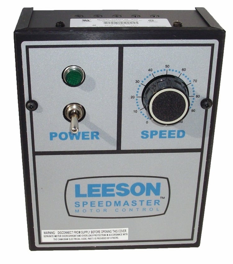
Figure 3. DC Motor Speed Controller.
PWM used for Battery Charging
With electric vehicles becoming more popular, the technology involved with the charging stations is advancing as well. Solar panels are also becoming a popular trend within suburban areas as a means to lower electrical bills or give back to the environment. As the battery begins to fill to capacity, the power being transmitted to the battery needs to be decreased. By using a PWM controller, the amount of supplied power can be accurately controlled.
Lowering the charger voltage would be problematic as the battery voltage would eventually be higher than the small trickle charge would require and the battery would begin discharging.
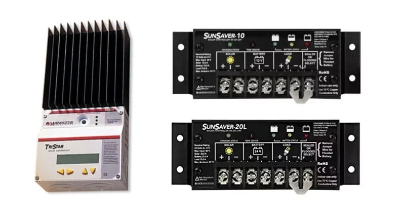
Figure 4. Solar charge controllers.
PWM Used in a VFD for 3-Phase Applications
A variable frequency drive is a device for controlling 3-phase AC motors. The VFD will produce a fixed AC voltage amplitude with varying frequencies to control the speed of the motor. Inside the VFD, the incoming voltage is converted from AC to DC and then back into AC using a series of high-power transistors to create a PWM signal that recreates the AC waveform. This application is slightly different from DC motor control as the duty cycle does not directly dictate a constant equivalent power applied to the motor, but instead is used to control how quickly the applied voltage will switch polarities in true sine-wave alternating fashion.
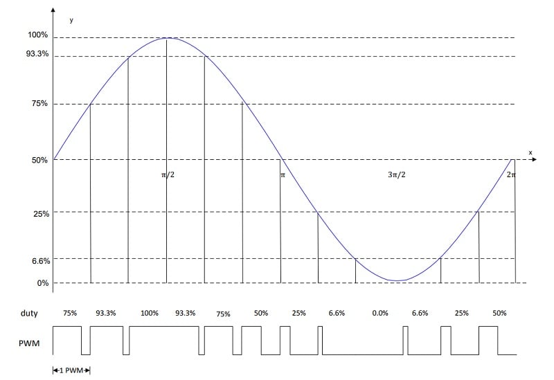
Figure 5. PWM is used to recreate a sine wave for AC applications.
PWM Generating Devices
There are many devices on the market that can produce a PWM signal or drive devices using a PWM signal with minimal input. For industrial applications, there are standalone devices that have a dial or analog input to adjust the speed. For installation, you just need to supply power and a motor, everything else is contained inside of the enclosure.
Some PLC manufacturers have outputs that can be configured to be PWM outputs, although note that relay outputs do not have the speed or service life to support PWM outputs. These outputs usually can’t drive large loads directly but they can drive solid-state relays.
Most microcontrollers contain multiple PWM outputs that can be programmed with internal functions requiring only a duty cycle and supplying a 3.3-12 volt output to drive transistors or solid-state relays for amplification.
Creating A PWM Signal
Creating a PWM signal will depend entirely on the device producing the signal. If using a PLC with a designated PWM output card you will need to provide a frequency and duty cycle value to the card over the selected field bus technology. Some PLCs may have supplier-provided function blocks that will have parameters that need to be set before operation.
Some motor controllers will accept an analog value in the form of 0-10 volts or 4-20 mA which will be scaled to output a duty cycle ranging from 0-100%. Microcontrollers like the Arduino use their digital outputs to provide PWM signals, simply writing an output command with an argument between 0 and 255 which represents the full duty cycle range.
Summary
As with any aspect of electronics, there is absolutely no single solution for all load control challenges. PWM is an effective solution for many load types, but the implementation must be chosen properly for DC and AC applications and must consider the response speed and power requirements of each individual device.
Copyright Statement: The content of this website is intended for personal learning purposes only. If it infringes upon your copyright, please contact us for removal. Email: admin@eleok.com